
Non-Linear Coil Winding Experiment
Terry Fritz 10-18-97
I have been experimenting with different types of coil windings. Using my computer-controlled Tesla coil winder, I made three coils. They were all wound with the following parameters:
300 turns 3 inches in diameter, wound on cardboard mailing tubes.
10 inch long windings on 12 inch long tubes.
#30 enameled magnet wire 0.0110 inches in diameter.
235.6 feet of wire. No top terminal was used.
Coils 1, 2, and 3. Click on image for large picture.
Coil #1 was wound with linearly spaced windings.
Coil #2 was wound with the winding spaced proportional to d=cos(x). In other words, the coil windings were spaced so as to give a linear voltage distribution along the coil. Assuming V is proportional to sin(x). (x is the distance along the coil). This coil has windings bunched together at the top.
Coil #3 was wound with the windings spaced proportional to d=cos(x)^2. In other words, the coil windings were spaced so as to give a linear capacitance distribution (turn to turn) along the coil. Assuming C is proportional to V^2. This coil has windings very bunched together at the top.
Details of Testing:
Cself was calculated from the measured inductance and the resonant frequency C = ((1/(2 * PI * Fo))^2) / L . I checked the test equipment with some older coils which I know well and everything checks fine. The oscilloscope has the standard 10:1 probe (100MHz) into a 40MHZ dual-trace scope. The inductance was measured with a hand held LCR meter that I use often and trust. The frequency was measured with a 100Mhz frequency counter. The coils were driven from a sine wave generator with a 600 ohm output Z. I also ran the coils with a 50 ohm square wave generator that can drive much harder but the results were the same. All the equipment is less than five years old and seems to work flawlessly. I tested the coils in a reasonably open space on a hardwood floor 6 inches above bare dirt. I tried the coils in other locations at various distances from the surroundings the results don't change significantly unless I get within about 2 feet from something big. As far as I can tell, everything is reasonably accurate. The field mapping experiment obviously had some variability but the general results I feel are accurate.
One thing that blew one of my pet theories to hell is that the quarter wavelength for a 235.6 foot long wire is 1043.7 kHz. All these coils exceeded that frequency considerably (so much for worrying about wire length vs frequency). I tried very hard to find a lower resonant frequency but it simply wasn't there. The fields around the coils were consistent with a quarter wave resonance so I am sure I didn't hit an off harmonic. It took me awhile to find it up at 1.6 MHz. All the coils were tested one after the other with no change to the test setup.
The results are as follows:
Coil #1
F0 = 1597.6 kHz
Inductance = 2.07 mH
Self Capacitance = 4.79 pF
Coil #2
F0 = 1815.7 kHz
Inductance = 2.16 mH
Self Capacitance = 3.56 pF
Coil #3
F0 = 1829.0 kHz
Inductance = 2.31 mH
Self Capacitance = 3.28 pF
Field Strength Test
The field profile around each coil was mapped at resonance to determine the shape of the field around each coil. This was done by placing a sheet of paper directly behind the coil and bringing a grounded rod near the coil. As the rod approaches the coil it de-tunes the coil and the field strength decreases. (As measured with a short antenna connected to an oscilloscope). The point at which the field strength decreased by 1/SQR(2) was marked on the paper. A signal generator drove the coils. The output was 5.0 volts peak-peak. The wave form showed very little loading at resonance.
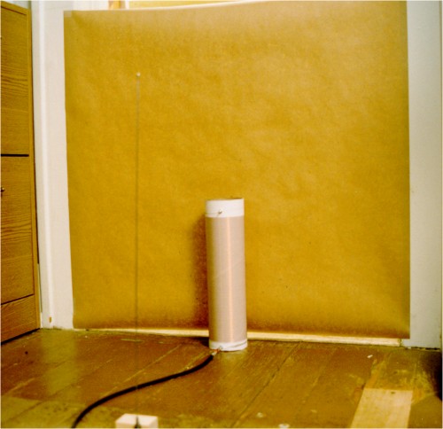
Front of field test setup. Note antenna in forground.
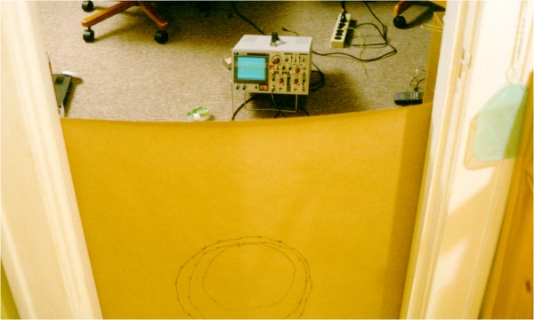
Front of setup. Scope used to determine field strength.
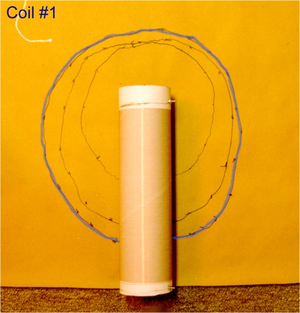
Coil #1 had an approximately 13-inch diameter field that was elongated along the length of the coil. No big surprise.
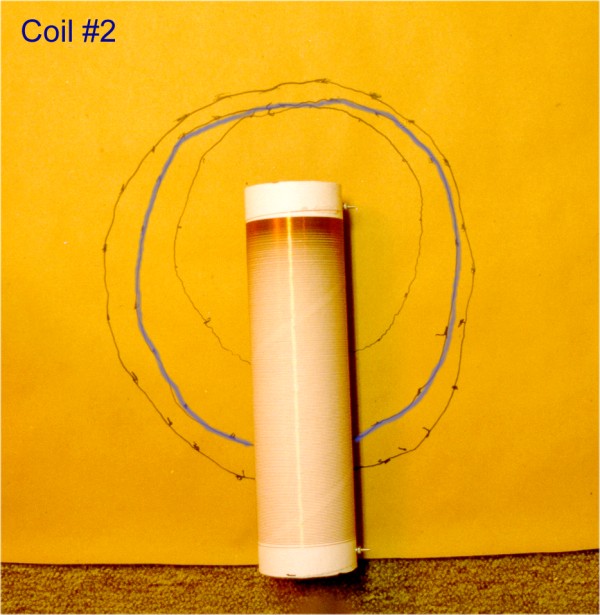
Coil #2 had a similar but smaller field 11 inches in diameter.
Coil #3 had a field that was very circular in shape. This circle was centered at the top of the coil windings and was approximately 8 inches in diameter.
Conclusion:
Coil #1 performed as expected.
Coil #2 appears to have succeeded in evenly distributing the winding to winding voltage along the coil without harming any other parameters (they improved considerably). Such a coil would be much less likely to arc between windings. It would also have better field distribution around the coil allowing higher voltages to be achieved.
Coil #3 has the lowest self-capacitance and the highest inductance. Theoretically, this is optimal but the field distribution around the coil would tend to promote early breakdown.
Terry Fritz
terryf@verinet.com