This paper describes tests that were done to determine the differences in performance between multi-gap and simple spark gaps used in Tesla coil primary circuits. The gaps were tested into a wide range of coefficients of coupling between the primary and secondary inductors.
Introduction: It has been long known that various designs of spark gaps can have a profound effect on Tesla coil performance. There are three types of gaps commonly in use. Simple gaps, multi-gaps, and rotary gaps. The rotary gap is not considered here. The performance of a particular gap on any Tesla coil system cannot generally be predicted. Some people find the simple gaps work well and others find their systems perform better with multi-gaps. This paper will explain the differences between the two gaps and will also demonstrate the importance of using a proper amount of coupling between the primary and secondary inductors.
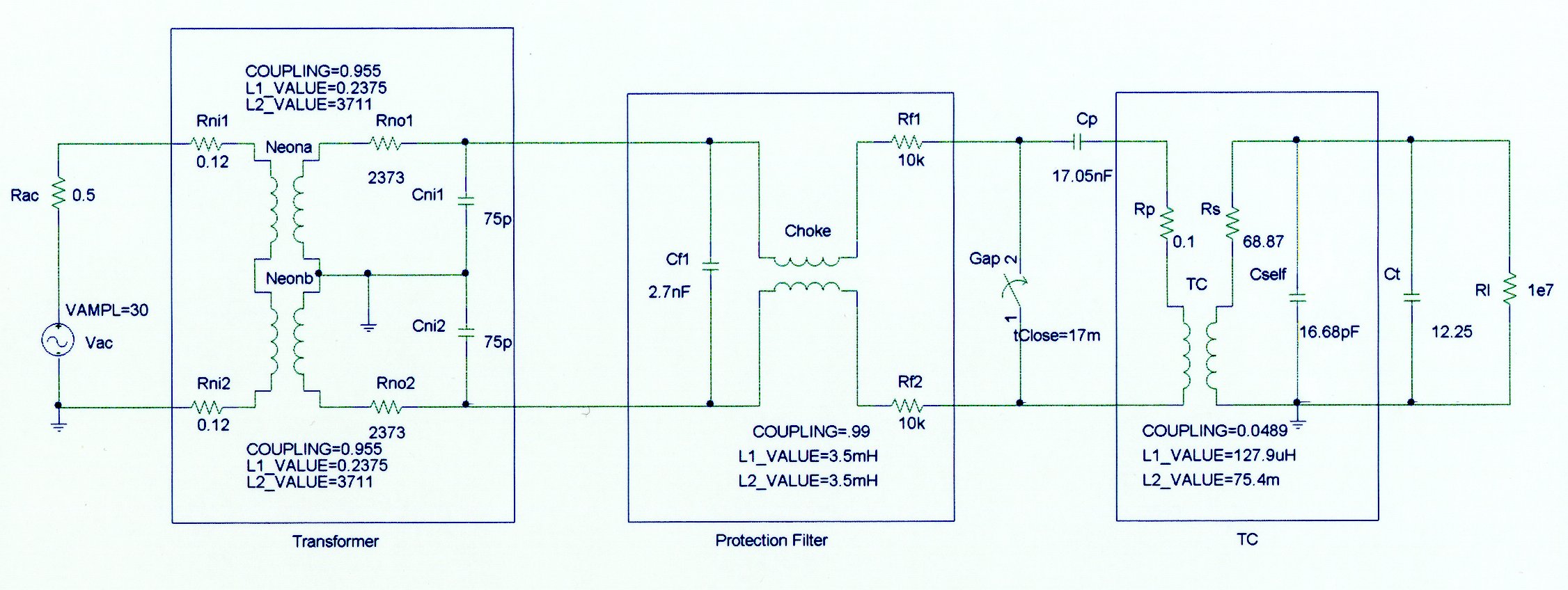
Test Setup: The test system used here is a conventional Tesla coil. A variac supplies voltage to a 15000 volt 60 mA neon sign transformer. The output of the transformer is filtered through a protection circuit and charges a 17nF capacitor. The primary inductor is a conventional flat spiral made from 1/4 inch copper tubing. The secondary is a 10-inch diameter by 30 inch long cardboard form wound with 1000 turns of #24 wire. The top terminal is a 12-inch diameter sphere.
Detailed System Schematic Diagram
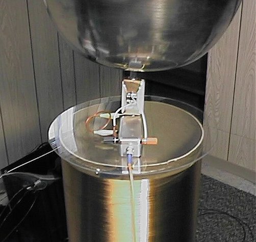
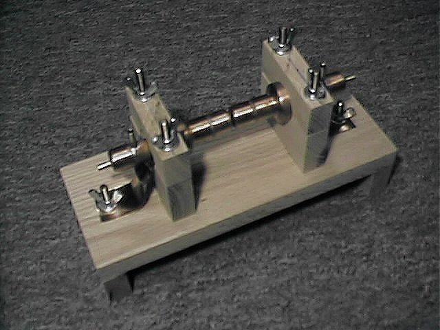
This coil is designed for research and also has some other features. The secondary coil is mounted on an adjustable wooden from so that the coupling between the primary and secondary can be easily adjusted. The various circuits in the coil are equipped with current shunts so that the real time currents can be measured and recorded with an oscilloscope. All of the primary voltages can also be monitored as needed. For this experiment only the primary capacitor voltage and the current between the top of the secondary inductor and the top terminal are measured. These two key points provide an excellent view of the coils operation.
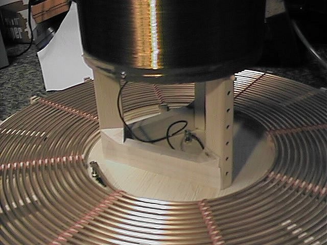
Adjustable frame to vary the height of the secondary
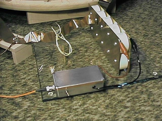
Primary cap and voltage transducer Current transducer
The primary inductor is tapped at 15 1/8 turns. This gives a primary inductance of 127.9 uH. The primary capacitor has a value of 17.05 nF. The resonant frequency is 107.8 kHz. The secondary inductor has a value of 75.4 mH and a self capacitance of 16.68 pF. The top terminal adds 12.25 pF for a total of 28.93 pF. The coupling coefficient of this coil can be adjusted and the values are as follows:
| Secondary Height (in) | Coupling Coefficient | Secondary Height (in) | Coupling Coefficient |
| 15 | 0.0226 | 7 | 0.0647 |
| 14 | 0.0256 | 6 | 0.0760 |
| 13 | 0.0286 | 5 | 0.0888 |
| 12 | 0.0324 | 4 | 0.1046 |
| 11 | 0.0369 | 3 | 0.1242 |
| 10 | 0.0421 | 2 | 0.1475 |
| 9 | 0.0489 | 1 | 0.1753 |
| 8 | 0.0557 | 0 | 0.2069 |
Simple gap made from copper pipe fittings.
The second gap was a multi-gap design made from 1/2- inch copper pipe sections. The sections were epoxied to a wood base and spaced with 0.007 inch plastic sections while the epoxy cured. For this experiment, four of the gaps were used for a total space of 0.028 inches. This produced a firing voltage of about 5000 volts as before.
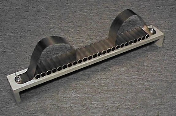
Multi-gap made from 24 pipe sections.
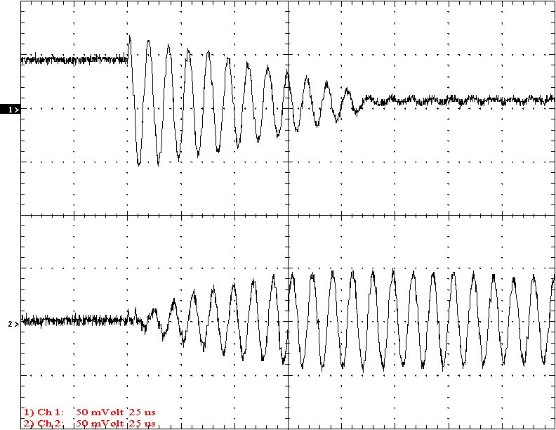
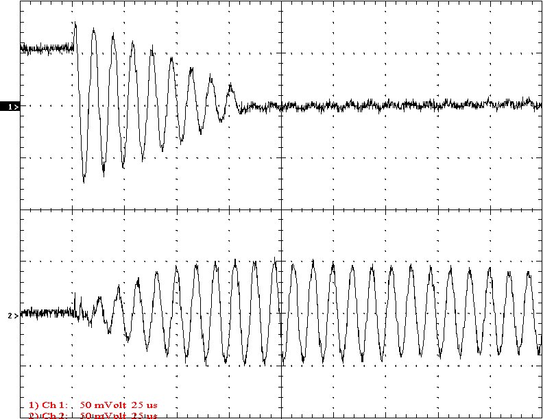
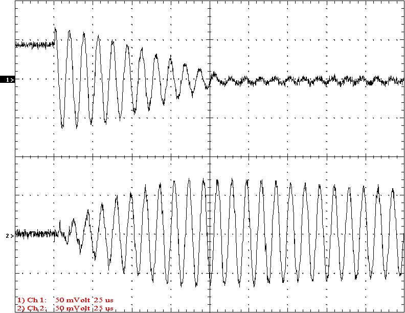
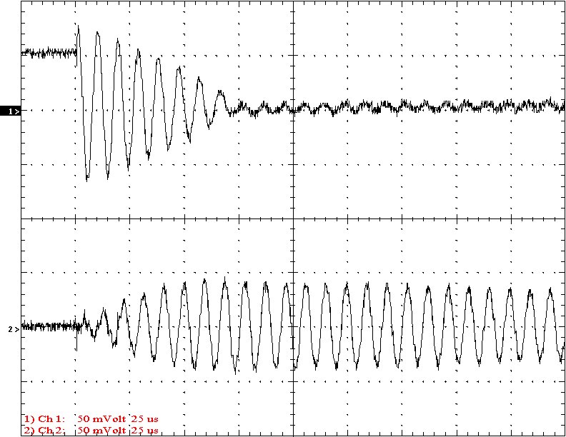
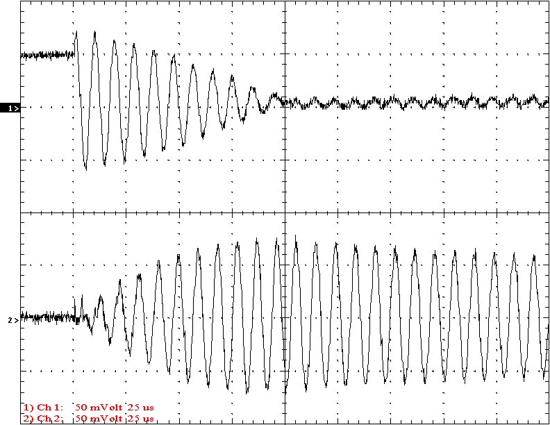
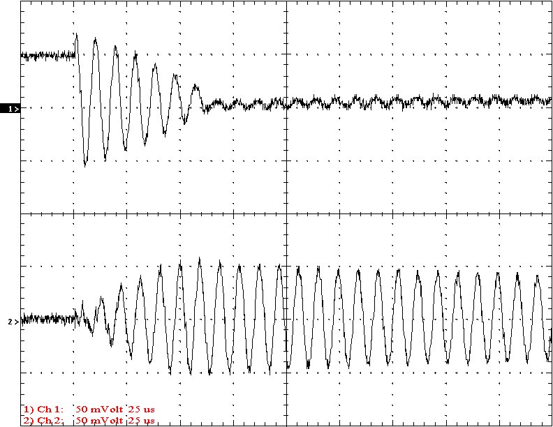
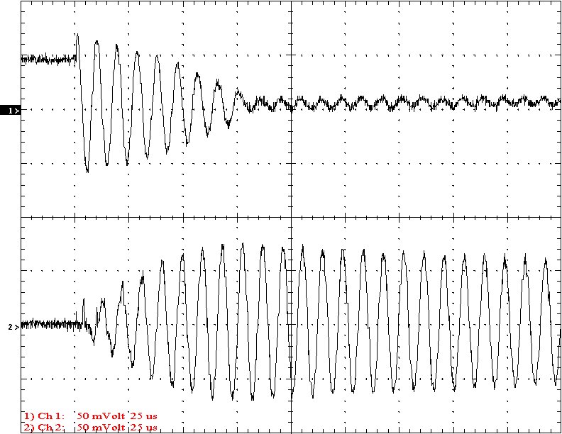
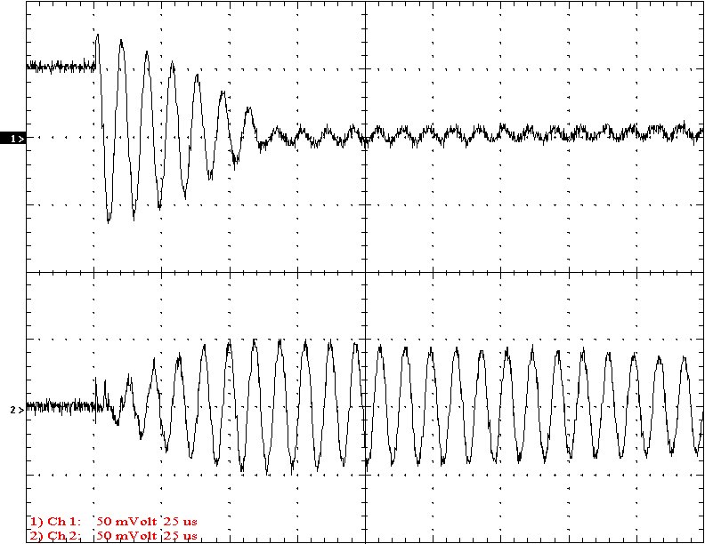
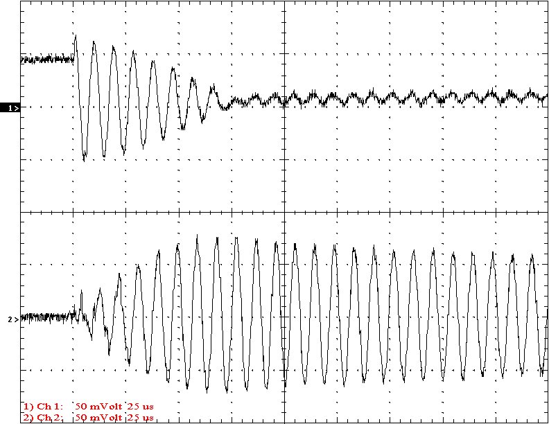
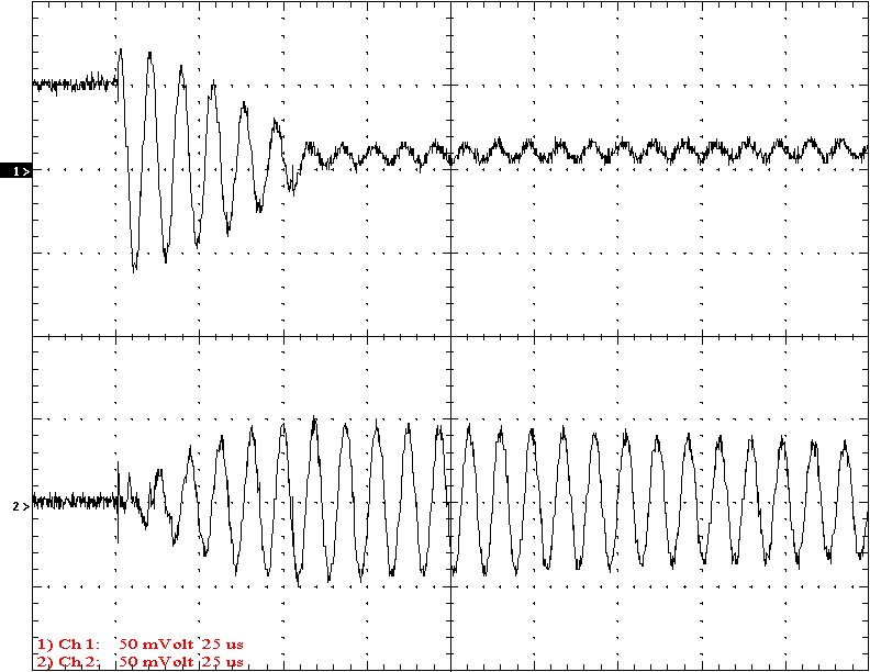
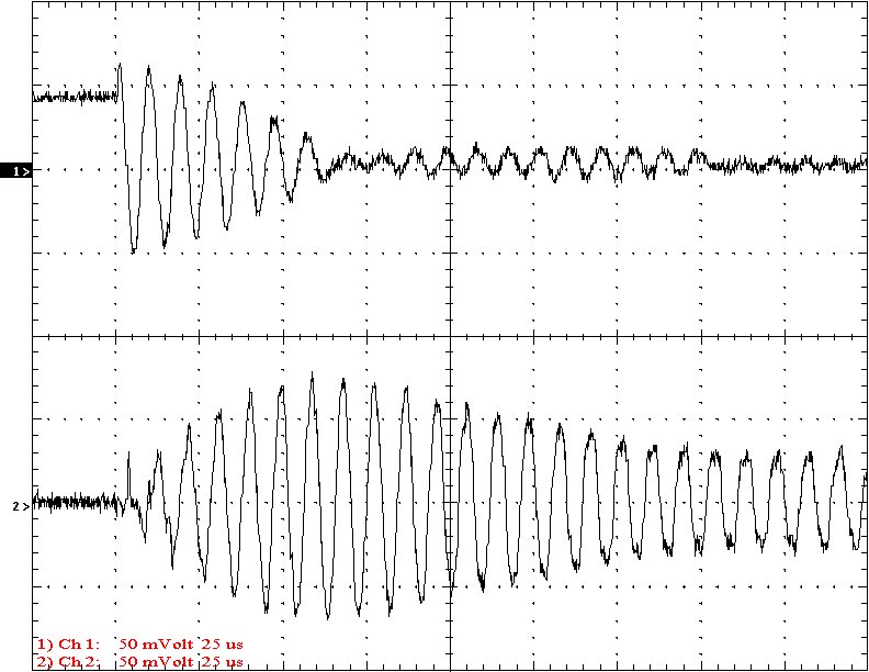
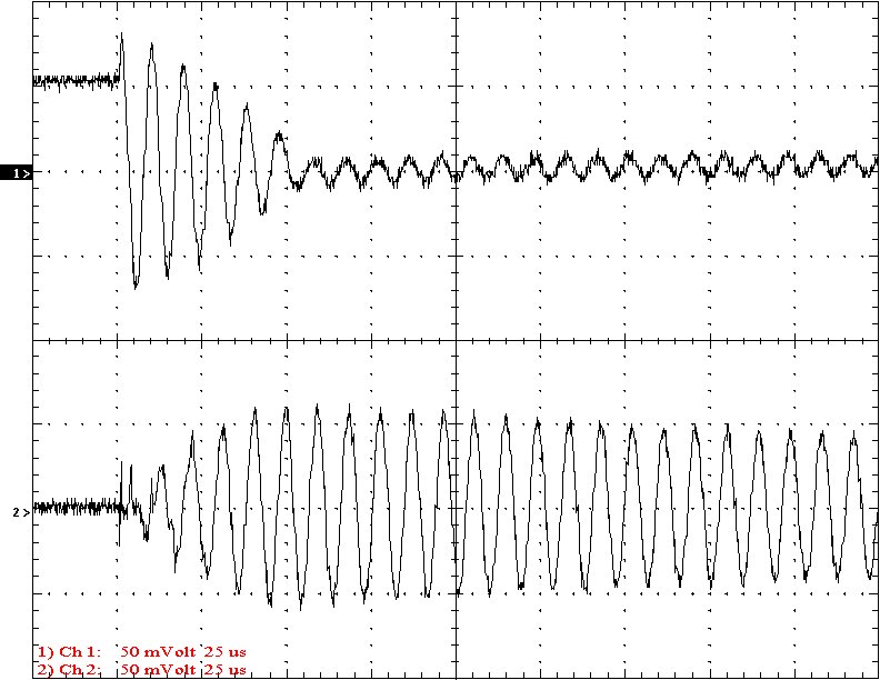
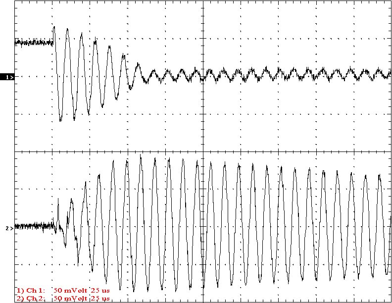
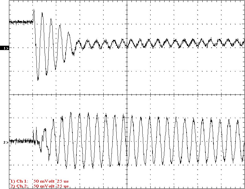
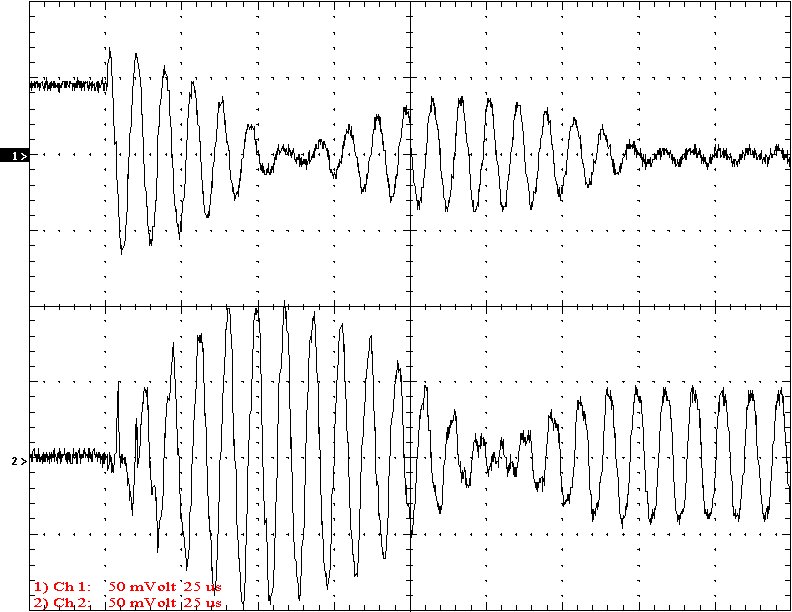
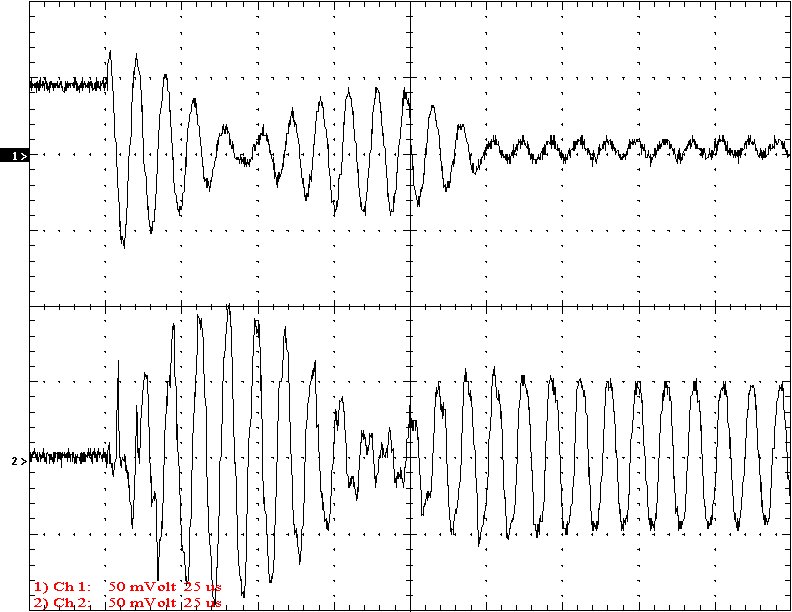
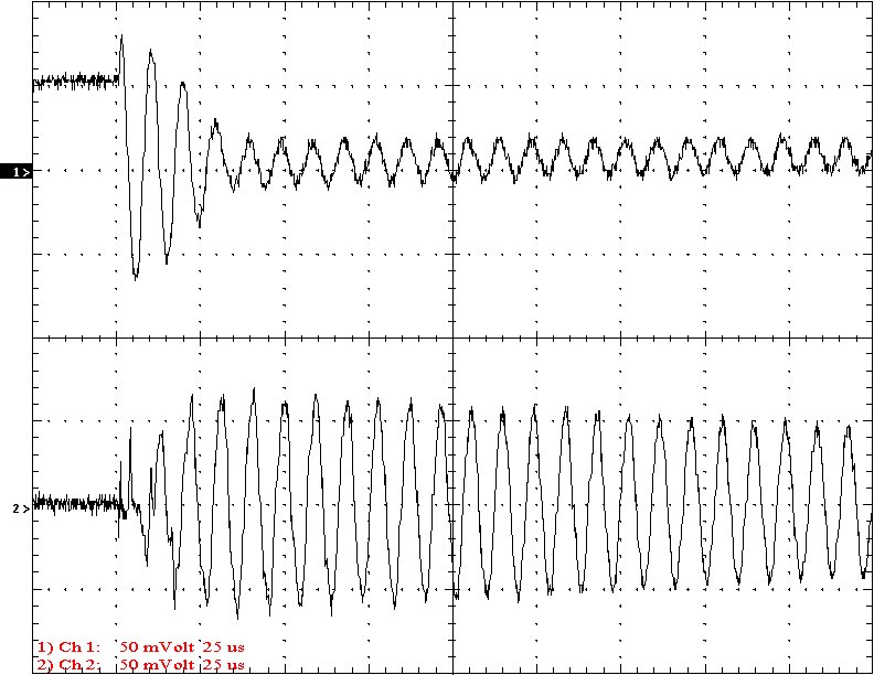
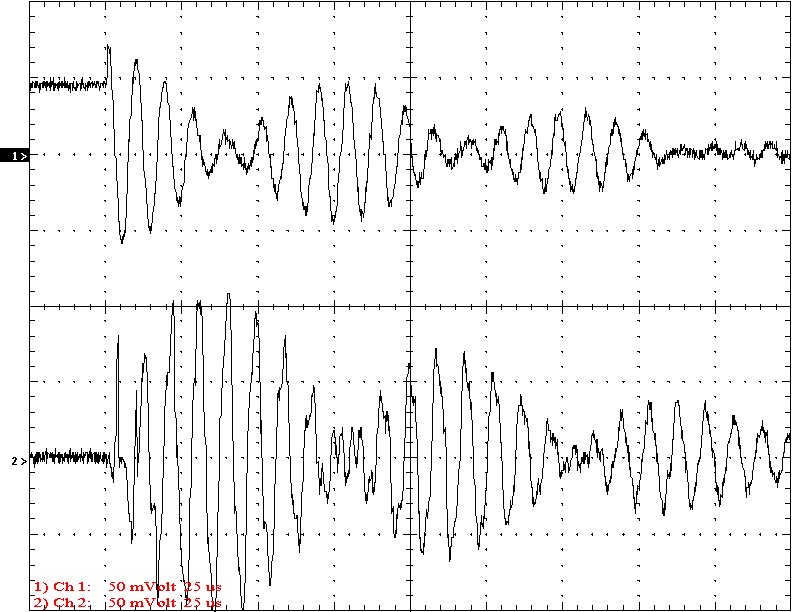
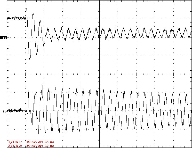
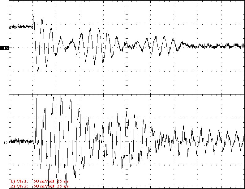
Results: The following 32 oscilloscope pictures show the affects of coupling on the multi-gap (left) and simple gap (right). The top trace is 5000 volts / division measured across the primary capacitor. The bottom trace is 5 amps per division measured between the top of the secondary and the top electrode. The photos shown are with no secondary breakout. Some of the high peaks may have produced some surface ionization judging by the increasing loudness of the coil.
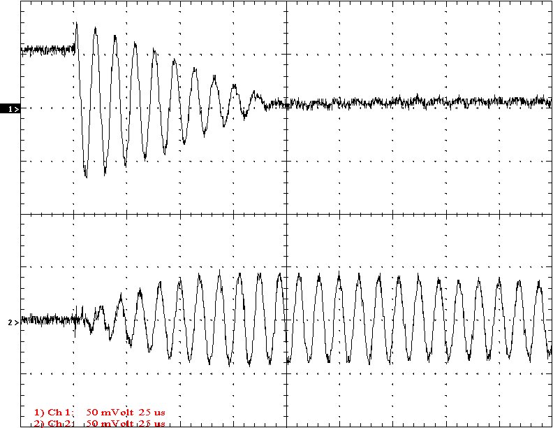
Multi-Gap K=0.0226 Simple Gap K=0.0226
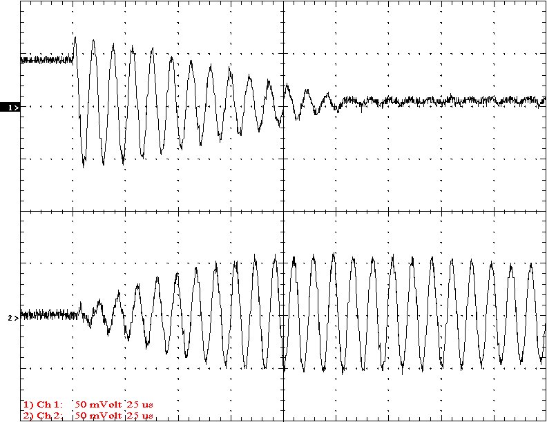
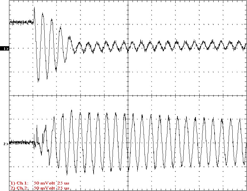
Multi-Gap K=0.0256 Simple Gap K=0.0256

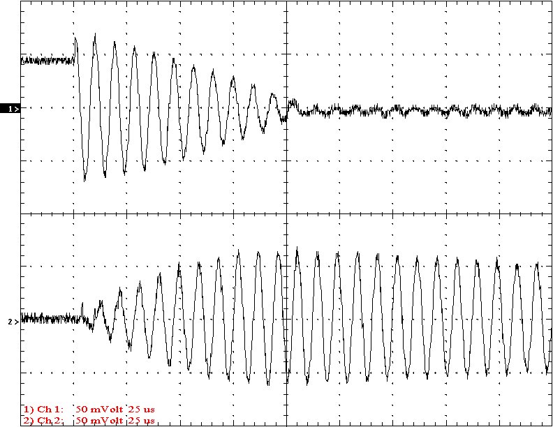
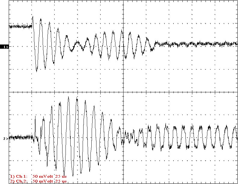
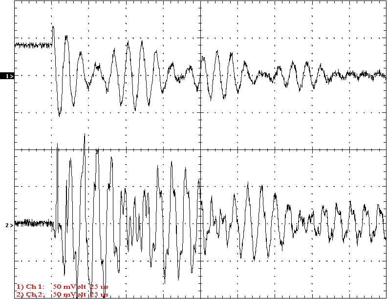
Multi-Gap K=0.0286 Simple Gap K=0.0286
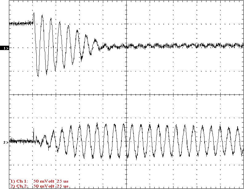
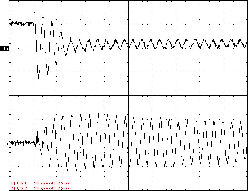
Multi-Gap K=0.0324 Simple Gap K=0.0324
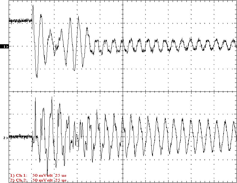
Multi-Gap K=0.0369 Simple Gap K=0.0369
Multi-Gap K=0.0421 Simple Gap K=0.0421
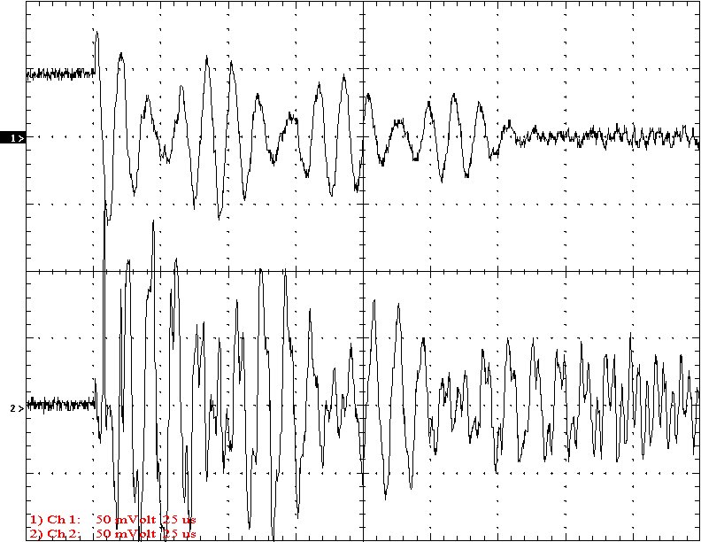
Multi-Gap K=0.0489 Simple Gap K=0.0489
Multi-Gap K=0.0557 Simple Gap K=0.0557
Multi-Gap K=0.0647 Simple Gap K=0.0647
Multi-Gap K=0.0760 Simple Gap K=0.0760
Multi-Gap K=0.0888 Simple Gap K=0.0888
Multi-Gap K=0.1046 Simple Gap K=0.1046
Multi-Gap K=0.1242 Simple Gap K=0.1242
Multi-Gap K=0.1475 Simple Gap K=0.1475

Multi-Gap K=0.1753 Simple Gap K=0.1753
Multi-Gap K=0.2069 Simple Gap K=0.2069
Conclusion: The results show that both the simple and multi-gap spark gaps can produce the same voltage levels. In fact the simple gap may produce higher peaks when the coupling is high. The multi-gap was much more stable over a wide range of couplings. But only when the coupling was pushed to near the point at which quenching was lost did the secondary current rise to a high level. This suggests that many systems that us multi-gaps may not have enough coupling to take full advantage of the gap.