Tesla Coil Spark Gap Operation Analyzed at High Frequency
4-5-98
Terry Fritz
This paper describes a series of tests and experiments, which analyze the voltages and currents in Tesla coil primary circuits. A newly developed very high frequency fiber-optic probe system was used to record waveforms at a bandwidth of 30MHz. The resulting waveforms show a vastly different mode of operation than was previously known. Instead of a simple switch, The spark gap appears to be operating through a series of very powerful high-frequency bursts during the conduction cycle.
It is generally believed that when the voltage across the spark gap reaches a certain level, current passes through the gap and super heats the air creating a virtual short across the gap. This short remains in place until the primary circuit losses energy and the super heated air region can no longer be maintained. At this point, the resistance is believed to rise and the gap "quenches" and the resistance returns to a very high level. Typical measurements performed with relatively low bandwidth equipment more or less have demonstrated this phenomena.
Typical voltage and current waveforms measured with a 200KHz bandwidth system
Top Trace – Voltage 2000V/div
Bottom Trace – Current 20A/div
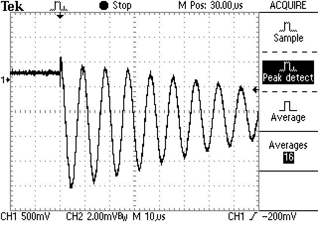
Typical wire antenna waveform
When equipment capable of much higher bandwidth is employed, this picture seems to change dramatically. When one terminates a quality antenna into the proper 50 ohm impedance, the fundamental signal seems overwhelmed by heavy noise spikes. This explains why a simple wire is often used as a scope probe to receive primary waveforms as opposed to a higher quality antenna system. The simple wire, and its very poor impedance matching to the input of an oscilloscope, attenuates these noise signals so that only a nice clean signal is left. If one uses a high bandwidth, properly terminated antenna, a series of noise spikes are seen (my testing was done without the secondary inductor in place).
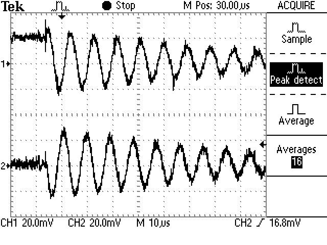
Antenna waveforms
Top Trace - Typical wire antenna
Bottom Trace - 50 ohm terminated scanner antenna
Careful examination will show these spikes appear as a series of noise bursts that occur at the peaks of the fundamental frequency. The power of these noise bursts is vastly higher than the fundamental waveform.
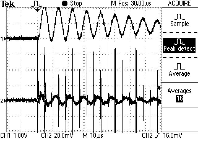
Voltage and current waveforms
Top Trace - Voltage form simple wire antenna
Bottom trace - Current seen with 30MHz fiber-optic probe.
Closer view of first cycle.
Close up of first current burst
Close up of second current burst.
I have found that these burst consist of ~50MHz signals that persist for about 100nS and then fall off to a much lower level and stop at about 500nS. The frequency of the bursts varies somewhat from test to test.
The power of these bursts is remarkable. Early testing has shown that, even at low voltage levels, these bursts may reach many hundreds of amps at the ~50MHz frequency. By far the most powerful burst is the very first one.
Typical scope photos often show this as a vertical line that occurs just at the beginning of conduction. My equipment has not been able to measure the level of this spike with great accuracy but it appears to be around 400 amps which is remarkable considering the relatively low 2000 volt spark gap setting.
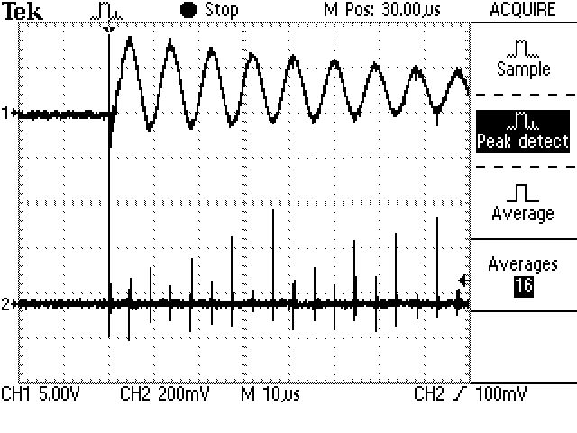
2.5MHz bandwidth, calibrated system
Top Trace – Voltage 2000V/div
Bottom Trace – Current 100A/div
What is even more remarkable is that the current outside this burst appears to be close to zero. In other words the full current in the primary seems to be conducted only in these short bursts.
Others and I have measured nice sine wave currents in the primary system before. So how can the preceding be true? I fear we have been tricked by the low frequency response of the equipment we use. The responses we have seen may be an artifact of the impulse response of those systems. These energy bursts can easily act as pure impulses, which will excite a low bandwidth system producing sine waves. We may have only been seeing the heavily damped response of these current bursts.
What are the implications if this is true? If the primary circuit is doing all of its work at ~50MHz and at hundreds, if not thousands, of amps at that frequency, everything changes! The conductors must be short, wide, copper strips. The capacitors must be able to withstand even greater stresses than we ever imagined. And the spark gaps... who knows? This would imply that a much better spark gap or other switching system might give much better performance. EMI becomes a major concern. At 200KHz it is easy to disregard EMI. At 50MHz all kinds of problems can arise.
Independent study is needed to confirm the results seen here. If these results are correct, the design and theoretical implications will be profound.