The new SSTC design provides new and exciting ways in replacement of gate isolation coils. It was found in the older MK4 SSTC that the gate drive signals were unstable and were moreso at higher frequency's. Even in the order of 100khz and lower it proved difficult to keep a stable drive wave. The result was incorrect firing of the gate drive causing all kinds of shorts and problems. Many coils were tried in all manner of combinations and it proved near impossible to keep a stable waveform.
I apologize for the poor quality of pictures though its the best I can take with my cam. I will take better scans soon.

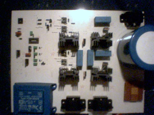
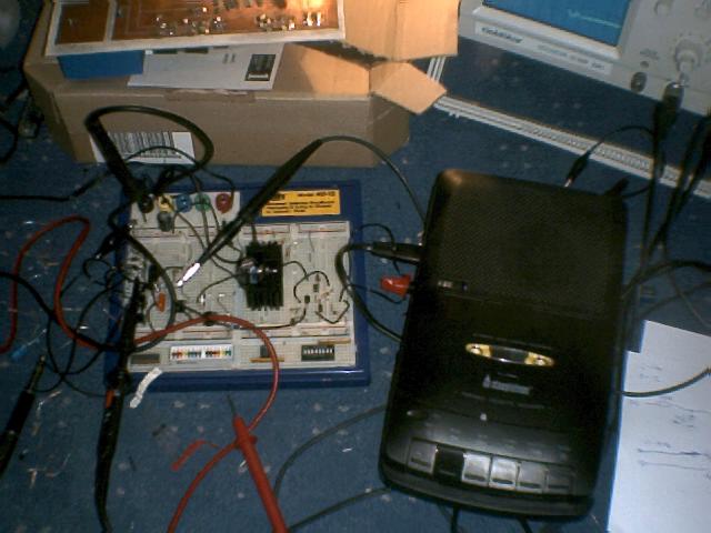
Above is the long waiting MK5 DIRECT DRIVE SSTC 90% completed in construction. Both control electronics and driver were merged into 1 PCB along with many other additions.
Top left is the same as the MK4 SSTC design. Bottom left is the 12VDC supply. To the right are the mains in and variac mains in connectors. Top right is the H-Bridge output connector. The center is the same H-bridge design as the MK4 with exception to the gate drive IC's inplace of the isolation coils. The big blue capacitor ( 400VDC 2200uF ) ensures enough amperage to place the SSTC into orbit should the mosfets short out :)

The 4 8pin sockets will house the new driver IC's. The IC's can withstand 500VDC floating output voltage so they are ideal for SSTC use. Each mosfet has its own driver IC. The driver IC's have a special fault protection circuit built in should any of the mosfets fail then they will shutdown until the fault is removed.
The IC's are ran from the 12VDC supply rail and the error input is feed via a 15V zener to each mosfet gate. This voltage is also then limited to about 18VDC to prevent overvoltage flowing into the IC. Should a fault condition short any of the mosfet gates to the mains VDC input ( often 100's of volts ) then a voltage will start to flow though the 15V zener giving a few volts rise to the error control input. On such conditions the IC is shutdown isolating it from the mosfet gates. The error out pin on the IC goes high under fault conditions. Currently this is not used on the MK5 design though I plan to connect all 4 Error outputs to a OR GATE which will probably be fed into a relay to trip the mains out. Note that the fuse will only blow under a total supply rail short. The error control will monitor each mosfet and should any of them fail or be overloaded for whatever reason, They will trip out the mains power. Hopefully saving the circuit from totally exploding :)
The new direct drive should hopefully solve all the problems related to using isolation coils. The gate drive signal will be much more stable and hopefully cleaner than isolation coils. Should the wave have spikes or overshoot then it could be possible to add a snubber to this also. I doubt it will be needed since the IC gate drive should be a nice clean wave.
Further changes to the control electronics involve using both output of the TL494 in inverting and none-inverting logic. Before the inversions was done with the driver IC's. The benefit of this adds a fraction more deadtime between fets phase changes. Some might think this is bad in some other respects though it should give more good than bad. The problem with the coilcraft coils is they held the charge in their "massive" inductance and delayed the wave ( which remained turn on ) even when the actual wave had turned fully off ( in dead time ). The actual result was a direct short across the mains DC supply rails via the power mosfets causing failure. Higher frequency caused more problems for this.
Of course there could be a solution to use self wound coils like many other SSTC designers use. Though like many other designs the waveforms suffer a great deal. I tried winding any coils as can be understood elsewhere in the SSTC pages. Though I could spend months finding a solution it was decided to construct a direct drive system. The SSTC MK1 used home made isolation coils and they did work well to some extent, Though I wasn;'t happy with their operation. I was also unhappy about the drive current being 2amps to get any sort of clean wave via the coils! There are many tradeoff between the 2 isolation coil designs. Though many weeks of experiments I concluded that coils were just not good enough for this application.
The auto tune system was given a replacement IC design to see how well it compares to the original setup. Audio modulation is on hold for the MK5. Even though I had very good results early on in the year ( see HERE ) I do not plan to make changes to this asyet. There is too much work gone into other parts of the design without new audio modulation systems. I have however added in some simple interrupter which was only a last moment thought, though the plan for this was to feed in a 1kHz wave into the control electronics to give the classic spark sound from a spark gap tesla coil. I am not sure if the idea will work since it was only a quick addiction though it might be adapted to audio at a latter stage, Roll on MK6 ;-) Shall I mention plans for MK7 yet ;-))
More will be added and updated as it happens over the next couple of days/weeks, time permitting of course. More circuit technical information will be added once it has been fully tested and proved functional.
November 3, 2003
Design work has started for the revised SSTC MK6 design! I've not even tested MK5 yet and already developing the MK6! Additions to the MK6 involve minor circuit corrections plus better error control.
Scope testing will start over the next few days for the MK5. All fault conditions will be simulated ( faked ) to make sure that nothing unexpected will happen when real power is pumped though it. Scope waves will be added to this page shortly after testing is completed.
November 4, 2003
After talking to tech support at International Rectifier they confirmed that under fault conditions I had described that the gate drive IC's can cope with upto 500VDC shorting on the H-bridge. This is great news and opens up a new design for SSTC uses! Many used isolation coils ( myself included ) to totally isolate the mains side from the control electronics. Which is great if you accept the problems related to this design. The problem of using direct drive was the problem of when the H-bridge shorts out ( or bursts into flames and explodes ) it would take out the driver IC's and most of the control electronics with it. Even though there is next to nothing in the control electronics side the only problem is killing the driver IC's. Since the IC's have a floating output they can withstand such faults. Also with the added bonus of they shut down isolating the gate drives from the control electronics.
More construction went on today and is almost ready for simple circuit testing. Changes have begun for the MK6 SSTC which will be based on the MK5 mostly. Once the particulars for the MK5 have been fully documented changes will be added to the MK6 which hopefully with be the final design for this range of SSTC. I will borrow a quality cam latter this week to take better images of the MK5 SSTC.
Humor ?
As a added bonus my father brought me a fire extinguisher just in case the perfect plan does fail. Safety is the "feature" of the MK5 though normally when things fail I can fly over to the plug and turn it off even before the mains fuse has chance to blow. Some say its the only time I move fast ( well apart from hometimes apparently ). I noticed point of the MK4 SSTC is that the fuse only blows when there is a short or for example draws more than the fuse rating. Which is all fine until the SSTC draws 2 amps less than normal and half the mosfets on the board are on fire and the supply is still turn on. Not really good unless you can move at the speed of light to turn the power off before it burns a big hole in the floor. The MK6 will detect such faults and turn off the mainspower via a relay or other similar method ( other than burning out the ground track on the PCB that is ). A friend at work said its nothing to do with the tracks, He seems to think its because the little electron people who walk down the wires start to become naughty and leave the orderly traveling path. No wonder my brain hurts...
November 9, 2003
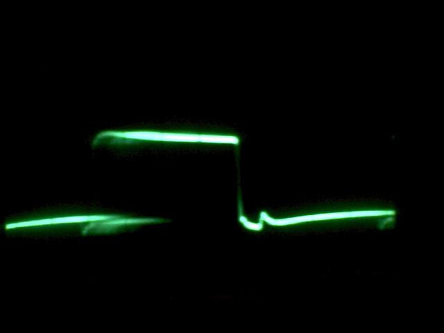
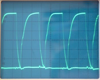
Over the last few days there has been some slight changes to the SSTC circuit. There was a few holes missing on the PCB which were easily corrected by the method of "The holes goes about there" with the PCB drill. Missing parts were added in and I first ran some power though the control electronics first. The below waveform was taken from the mosfet gate drives unloaded.

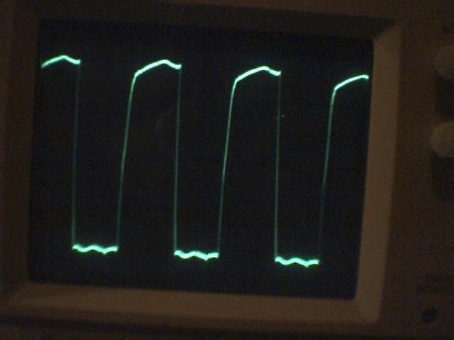
The above image is taken with 12VDC flowing though the H-bridge under a 100R resistor. The wave gets pulled out of shape slightly but is still perfectly acceptable. The slight distortion is half down to supply rail noise which I will take into account on the revised MK6 design. The TL494 output doesn't quiet make it down to perfect ground and stops short by around 0.2volts above ground. This is not a problem since the driver IC's need around 3 volts min for a logic 1 turn on.
Voltage was increased to around 30volts and the waveform remains stable.
November 11, 2003
I have plans to revise the control electronics soon to provide much better control of the driving wave. The 494 has too many shortfalls to make it stable in the current design. The wave generator will be a totally new concept with much improved control and stability. Protection for both overvoltage and overcurrent sensing will be *maybe* added to the current MK5 design for testing. The idea is to monitor all forms of shorts on the mosfets and shutdown all drivers and turn off the mains input. In the event of a mosfet short the circuit will totally turn off and hopefully save the last 3 mosfets of the H-bridge. All the new modifications will be tested out on the current MK5 design. I may not build the modified/revised MK6 board since I plan to totally redesign the whole setup and layout with many more modifications and safety features.
MK5 is waiting for parts still though scope testing will carry on and some circuit alterations can be done meanwhile. More scope waves will be added soon. The MK5 has had some minor circuit changes while experimenting with the control electronics. It is possible the 494 will be replaced by a small plugin board which will house the new prototype control electronics. All new designs will be added to the MK6.
The MK6 was supposed to have all the modifications of the MK5 though this is still possible I plan to build a new layout to the board to make it more compact. It will take some time to test out the MK5 fully, it will also take some time to design the new MK6 board. If all goes well the MK5 should have some real power-up tests!
November 13, 2003
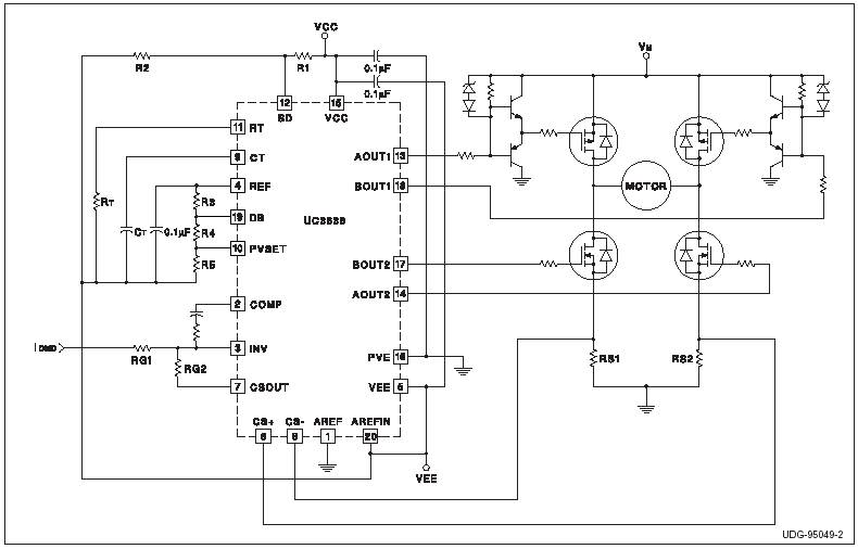
Above is a simple example of a Direct drive circuit using the UC3638 PWM motor control IC. This chip is perfect for anyone who wishes to experiment in Direct Drive SSTC's. Not only does the IC had Current sense pins (CS+/-) it is programmable with deadtime on the DB pin. Another good advantage is it will also go into 100'a of kHz which is perfect for SSTC use.
This design is much alike to the MK5 SSTC design although the new MK6 design will use more common parts and be a much more adaptable circuit when finished.

After 5 hours of "designing and frying" I built a simple 555 timer circuit. The 555 is of course a common timer and very flexible. Here I added in a rise and fall deadtime using a 74HC14 inverter and a few other parts. The idea is just to add a small delay between rise and fall cycles (deadtime) to prevent crossover shorts on the H-bridge.
Above is the breadboard circuit on test and also the scope waveforms. The problem with adding deadtime in this way is that the mark-space ratio is alerted slightly. But this is easily corrected by a small variable resistor on the 555. The duty cycle is guessed to be around 45% with a 5% "deadtime" between the next rise and fall of the cycle.
To the left of the test circuit are 2 large presets. These can alter the deadtime on either the rise or falltime. I didn't know exact values and the math behind it all is way over me so I just built it all with presets. There is a preset on the 555 also (hard to see on the image) which alters the mark-space ratio of the 555 to correct the deadtime "error" and give a perfect 45:45 squarewave. I don't know the actual delay time so it is hard to say is the mosfets gates will charge/discharge in the deadtime window. I will know more when I integrate this new 555 design into the MK5 SSTC. I would imagine the timings to be pretty close already to what they need to be. I guess the window is big enough for the gate changes, though this can be easily altered during next testing.
I plan to draw the design out on paper and build a quick veroboard version on this to plug into the MK5 control electronics. I will make a small adapter so it plugs into the 494 socket. Hopefully this will give a much easy design for the MK6 and give much better results. All is looking good!
Casualties in this test was a LM393 comparitor, the first one didn't like running at high frequency's ( before I used a logic chip) and the second I plugged in by mistake ( I thought it was a 555 ). Using a LM393 inplace of a 555 timer does not work well and does not give nice crisp squarewaves. It also gets a fair bit warm and I have a backwards imprint of LM393 on my finger which can never be good.
November 14, 2003
Today I built the test audio modulation circuit. This just uses a simple BC327 transistor and a few diodes to convert the level to something the 555 timer can use. I found that running on a 5VDC supply rail that anything under 2volts or over 4volts would cause distortion on the square wave. For this reason, and to keep the correct frequency, the 327 was pulled 2 volts above ground and was upper limited to 4volts. This was done using simple voltage drops across a series of 1N4007 diodes. The base of the 327 has now in effect got 2volts on all the time. This gives 2volts on the control pin of the 555 when audio input level is at 0 ( or off ). As voltage rises on the base of the transistor ( with audio ) the 327 boosts the voltage up slightly and has a maximum limit of 4 volts to the 555. The input to the 327 is feed via a 10K resistor so input power needs only be low. A typical audio line level of 500mv will be used. Anything too high and the audio level is "clipped" which of course Leeds to distortion and over modulation.
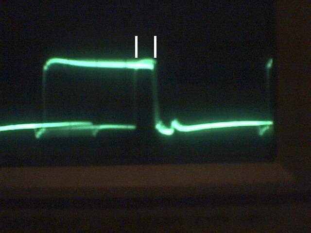
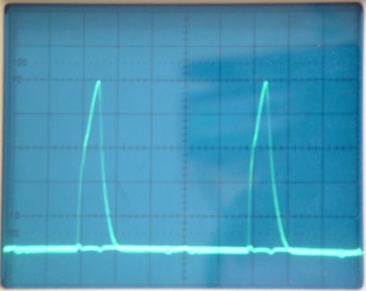
Here maximum volume was placed into the modulator circuit. This gave a lot of distortion. The small white lines on the above image are the deadtime circuit doing its job and cutting off the overvoltage in the modulation circuit. This prevents any shorting problems on the output stage. You can see when the bottom going right spike reaches a too high of volume it is clipped by the deadtime control. This configuration makes the audio modulation "indestructible" to the H-bridge. The previous image has no clipping and thus gives a very clean sound!
The headphones were connected across the 2 outputs of the 74LS14 IC. A inverting and none inverting output is used to drive the headphones in push-pull operation. The circuit operates in Class A mode since there is constant power going to the headphones at any time. I doubt phase modulated Class A will win any awards but its a interesting experiment to try. And with only 5% crossover distortion it can't be bad ;-)
This new design will not only start by giving me the driving wave for the MK6 SSTC, but it will also include adjustable deadtime and with the added bonus of audio modulation. Who would have thought a 74LS14 and NE555 chip could be so simple and have so many interesting uses :)
I hope to soon have the design in some form of order soon. At the moment the design is on multiple bits of paper so its all a mess at the moment. If I can't get the hang of a schematics program then I will hand drawn the design and upload that when ready. Well, I understand it even if nobody else does ;)
November 21, 2003
Modulation circuit totally revised. Less parts needed now and output volume is a lot better now. Protection circuit is no under testing. Its proving troublesome interfacing various inputs and outputs at all kinds of logic levels and currents though the test circuit so far is proving to be working correctly.
Each mosfet will have its own "trip" circuit. This trip will be connected to a small LED which will latch on under faults. So far faults are direct short of gate to ground. Direct short of S-D where over current is detected. Overvoltage on gate above ~15VDC. IT is possible that the mosfets could be subjected to BEMF pulses which could overload the gate voltages. Hopefully the circuit will shutdown before the voltage rises to destroy the device. Each mosfet "trip" will also latch and hold the other 3 mosfet drives in "error mode" where the H-bridge is totally shutdown. Should 1 mosfet go totally short then the next cycle could destory 1 or more other mosfets. Shutdown should help prevent expensive failures.
Work is currently going into complex error testing which will take a few days to compleate. When the design is fully working I will move onto the new PCB design. I hope this will be compleated over the next few days.
December 19, 2003
MK6 is 90% built. The final parts arrived yesterday so the MK6 should be finished over the next following days. First scope results will be posted when the circuit is compleated. I hope to have the test results by the end of next week.
January 2, 2004
A good start to the new year. The MK6 is now built and scope waveforms look very promising. I will upload them shortly. The auto protection seems to be working a little too well at the moment which needs to be looked into. Since the circuit was designed "out of my head" some values for resistors etc. might need a small alteration. I have not yet tried any coil experiments though I've had power running though the system under a 8R resistor and all looks well. The over current protection trips out at around 40VDC input so that's about 5amps which is about correct. I will probably widen this limit in the future. One small "under thought" was I totally forgot to add the auto-tune circuit in there. I plan to build a small add-on board to hold the additional electronics. This will work out good in some respects since I can have a "plug and play" auto turn circuit. More testing will be done over the next few days until I get used to the new circuit and how its operating. I also need to design a better reset circuit since the only way to reset the circuit is to power off totally for 5 seconds. Which is good in some respects but its too annoying, I guess this design was a little "too" over safety conches.
May 15, 2004
I had time to send on the MK6 DDSSTC this week to investigate the tripping out problem on powerup. It looks like I have a batch of faulty driver chips, which im not supprised since I got them from a guy on Ebay some time ago! The driver chip is generating a ERR on power up which shouldn't happen since the ERR output should only be 0.8volts and its 11.75 volts on a a12.25 supply rail. So something is very wrong there. The protection circuit work correctly if all the driver chips are taken out and you manually pulse the ERR line.Time to order some more chips!
I am also now thinking of a MK7 which I will include the auto tuning circuit which I had on the MK4 some time ago. I am also thinking of building the MK7 as a surfacemount board to save time in drilling millions of holes. The main H-bridge will still have to be drilled. Though it could help reduce construction time and make the board smaller.
Soon I will test on my old secondary coil, once happy with result I will construct a optimal coil.
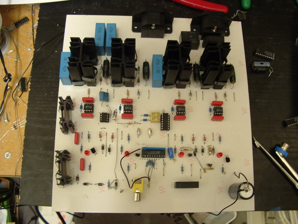
At last a image of the new DDSSTC!
At the back are 2 connectors, one is the DC mains in and the Primary coil out. Below that is the 4 IRF460 mosfets mounted on the classic sized heatsinks which I like to use. The 4 4watt (green) resistors are to set the current sense of the driver chips. Below that are the 4 IR2125 driver IC's. The chip on the left just below the driver IC row is a TLC555. I've been experimenting with this and soon I will use a "nicer" clock circuit. The new design will replace the 555 and allow any frequency from 1kHz to around 20mhz. The chip in the center and related parts is the deadtime controller circuit. This allows me to manually set very accurately the deadtimes.
The bottom IC is simply a tri-state buffer which takes care of interfacing the error voltages. Each LED is directly under a mosfet (sort of) and each LED will light when the corresponding FET generates a fault condition. Each LED is latched on via a set of 2N5060's which in turn latch on a 5th which trips out the relay at the back of the board to turn off the mains input.
There have been a few mods to the board which help make things run a little smoother as you can probably tell from the image. At the bottom I have a audio input connector for the Audio modulation of the 555.
Overall the board seems to be working well on the bench. Once I have the new clock generator circuit built I should then be able to start taking some powered up tests :)
As I said before since this is a large board with a lot of holes to drill, I plan to build a SMT version which will hopefully be the final MK7 Design. I've noticed that theres a 0.2volt drop across the board on the 12V rail which I am not happy with, theres also a problem found on the ground rail. Even though the tracks are like 1cm wide its amazing the voltage still manages to drop across such a large track! All these little findings will be corrected in the next design. I have also noticed theres what seems to be a random spike on the driving wave which I haven't traced yet. It probably down to the wire mess around the TLC555 which is causing it. This will be also corrected before the main powerup tests are done.
May 21, 2004
A few more tests today and a small mod to the trip circuit to make it even better.
Testing was done under a 3.3R 150watt resistor.
Circuit was set to trip out at about 1.3amps. Around 4 volts input drew around 1.4amps - Circuit tripped out - Test passed!
Mosfet gate short to ground - tripped out -Test passed!
Mosfet gate short to mains DC IN - Tripped out - Test passed!
The mosfet gate voltage is set to trip out at anything over 15VDC on the fet gates. Of course any gate shorts will also trip out, plus any over current shorts will trip out.
H-bridge was loaded with 100watts constantly for 30mins. This was around 4amps at 15VDC input at about 2mhz frequency. Heatsinks got warm after this time.
May 23, 2004
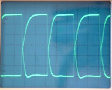
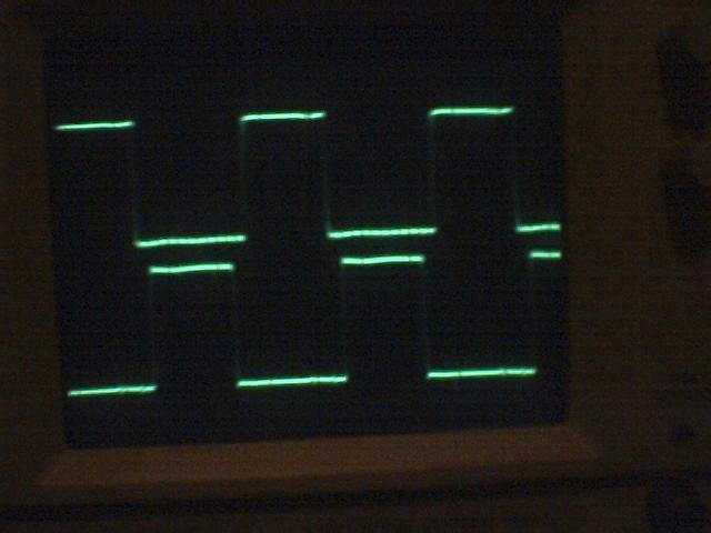
Above is waves raken from the mosfet gates. The image on the left is the deadtime set to min. You can see that around 5V (2V/DIV) that the H-bridge shorts out. This would casue the mosfets to heatup and around a 80% direct short accross the mains DC input to the H-bridge.
The image on the left is deadtime set to a maximum. I can adjust anything between the 2 extreams with the adjustable deadtime controller circuit.
The image above is the normally adjusted deadtime. Where ON/OFF periods cross as they should on the ground line.
The rise upto around 6V is a sharp fast rise which is what is needed. After 6V the wave slows down and give the arc look. This is no problem though I would have liked a sharper wave. The fall time isn't too bad either.
There could be many reasons why the waves arc off at the top. Since I didn't have this problem on the MK5, I assume its down to capacitance on the PCB tracks.
Now the circuit is running as expected, I plan to totally redesign the whole board. I am working to simplify the circuitry and also to make it a Surface Mount made board. The overall new circuit will be a lot smaller. I will probably cheat and add a small fan over the heatsinks on the new design just to aid with cooling rather than using larger heatsinks.
I plan to run 300watts though the H-bridge for 10 seconds to make sure things are running ok under a massive load. I can't run for any longer since I only have a 150watt resistor. This will be around 30VDC input at 10amps. Latter I will try and run the H-bridge at 230volts and load with a few 100watt mains lamps. If all goes well there will be no track melting, and no arcing on the PCB tracks :)
More to come soon :)
Chris