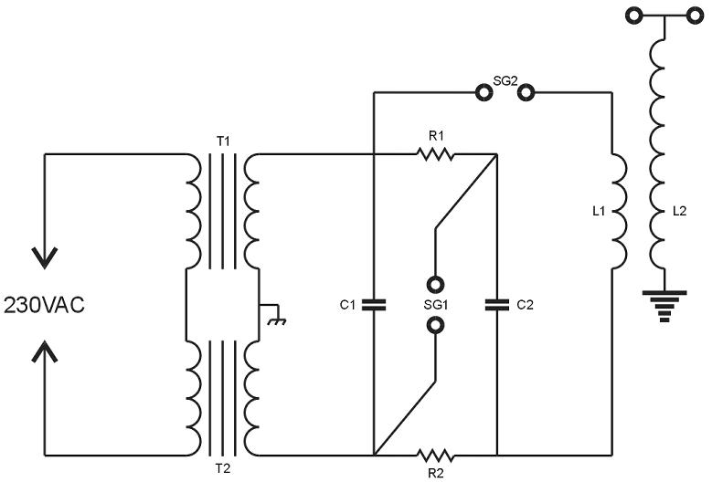
T1, 2: 2400VAC microwave oven transformers (120VAC primaries)
SG1, 2: Air blown spark gaps made from standard 3/4 inch copper pipe fittings
C1, 2: 94nF, 8KV MMCs
R1, 2: 100 Ohm, 55 Watt wire-wound power resistors
L1: Tesla coil primary
L2: Tesla coil secondary
This is a schematic of my experimental Marx / Tesla coil. The principle is simple. MOTs T1 and T2 develop 4800VAC to charge capacitors C1 and C2 in parallel to a peak of roughly 6KV. When spark gap SG1 fires, the capacitors are instantly switched into series, halving the total capacitance but effectively doubling the potential across spark gap SG2 to about 12KV. Once SG2 fires, tank circuit operation is just like any other disruptive-type Tesla coil. Wire-wound power resistors R1 and R2 provide RF isolation between the two tank capacitors, but allow them to charge in parallel at 60Hz. The 55W resistors are inadequate. They glow red hot after a few seconds operation. I plan to replace them with chokes or perhaps bigger resistors.