555 Interrupter
The interrupter is used to remotely control the duty cycle of the IGBT bridge, and allows you to pulse the primary circuit with currents vastly exceeding the continuous current rating of the devices. Complete control of the on and off times also allows the RMS current draw from the mains to be controlled.
MY SETUP
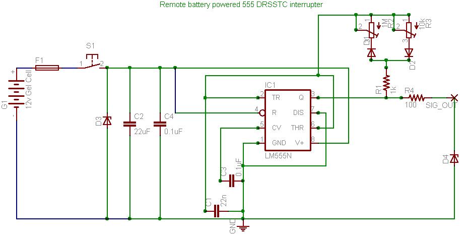
This circuit is by no means original, I copied it directly off Steve Ward, while adding a few of my own tweaks. Firstly, I am using a 12v gel cell battery, which will allow me to have a longer interconnect between the interrupter and the controller board (see next paragraph for an explanation why I would want this). The battery is fused at 500mA, not to protect the 555, but the battery itself. I have also added 15v zener diodes to hopefully protect the input and output from any induced HV spikes caused during operation. NOTE!!!!!!! The values for the timing capacitor and timing pots in the above circuit will provide you with an interrupter completely useless for this work! See below for more appropriate components.
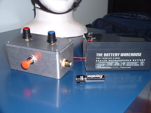
Here is the interrupter, housed in an Aluminium box. The two top knobs control on and off times, the red button is the power switch and the gold RCA socket (It just HAD to be gold :) is for connection to the power controller. I have constructed this part of the design carefully, because there is no reason why this interrupter can't be used for any coil from small desktop devices to huge multi kW coils throwing 20 ft arcs in the future! I hope to never make another one of these, though I may need to change the timing capacitor inside the box for different setups. This is also why I opted for the 12v Gel Cell, rather than a single 9v battery used by others - it has the juice to supply a longer supply line required for larger coils.
Current Specs:
Timing Cap: 10nF
On-time POT: 100k - yields 10uS to 800uS on times.
Off-time POT: 2M - yields 10uS to 16ms off times.