CNC mill
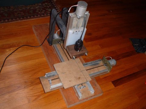
Theres a picture to get you started ;)
All material recycled except: two cutting boards, one 3' threaded rod (1/4"
20TPI)
HP Laserjet II printers rock ;) go find some if you can..
Im estimating the stepper are 60-80oz/in because of size and some ratings.
 |
First attempt at making the ways (rails/sliders). In this first design the white HDPE (cutting board) was kept from moving sideways by the black anodized aluminum plates that are rived to the 1" aluminum channel. The problem was the lack of rigidity in the plates, if id used 1/8" or thicker it probably would have been fine. I came up with a new way of doing it as youll see below.... |
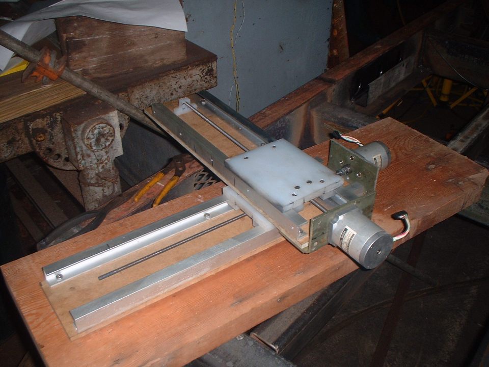 |
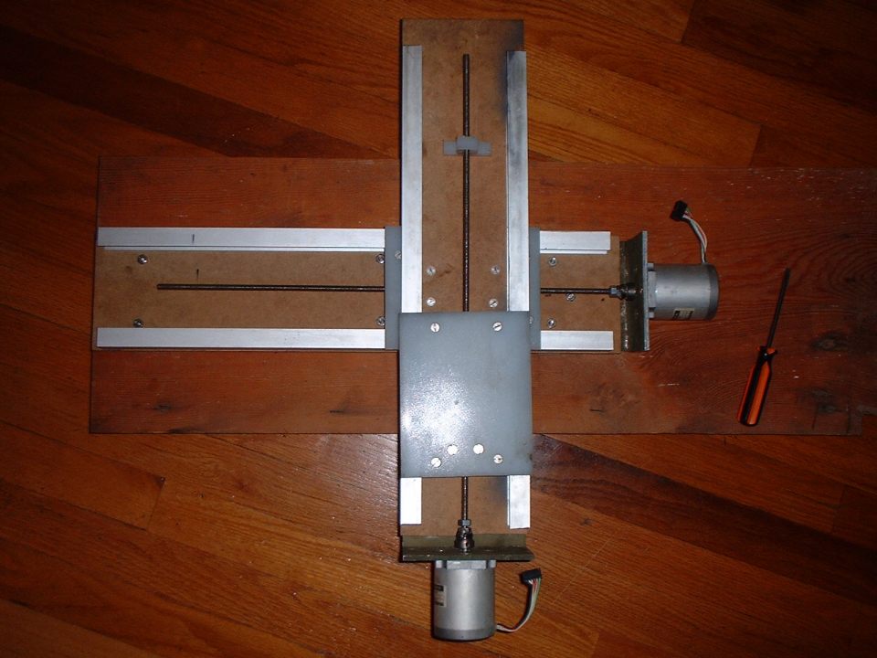
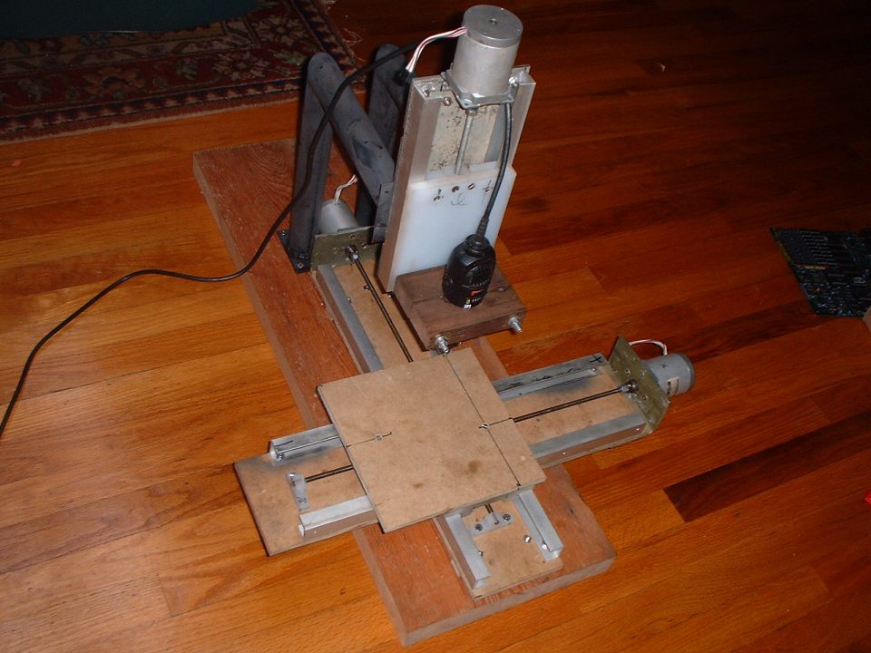
Here is the (alsmost) completed X and Y axis, the rails are now kept in place by the lower clamp pieces of HDPE which had the corner routed out with a table saw. |
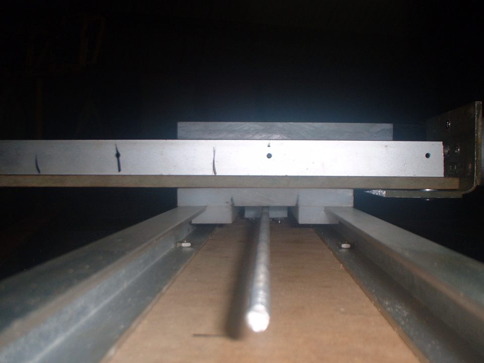 |
Here is a better view of the slider assembly, there are semi slots in the bottom clamp piece of the slider so I can tighten it up really easily. In the middle is the nut holder I made from another piece of HDPE, it has a hole and slot drilled into it then bolted to the top of the slider. |
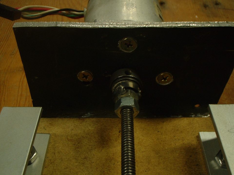 |
This picture shows the collet/adaper piece I made. The rear part is a collet (with set screw) from the HP Laserjet 2 printers that I also salvaged the stepper motors from. A nut was welded to the front of the collet and then another nut counter tightened against it to hold the threaded rod in place. |
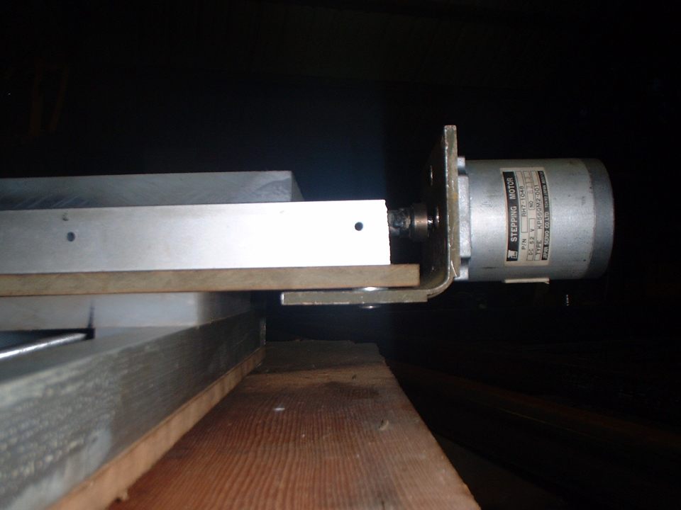 |
Side view of the motor mount assembly, its 3/16"" aluminum plate that I bent in the vice. The part number on the motor is: RH7-1048 All it lists for specs: 5.2v, I measued the resistance at 4 ohms. |
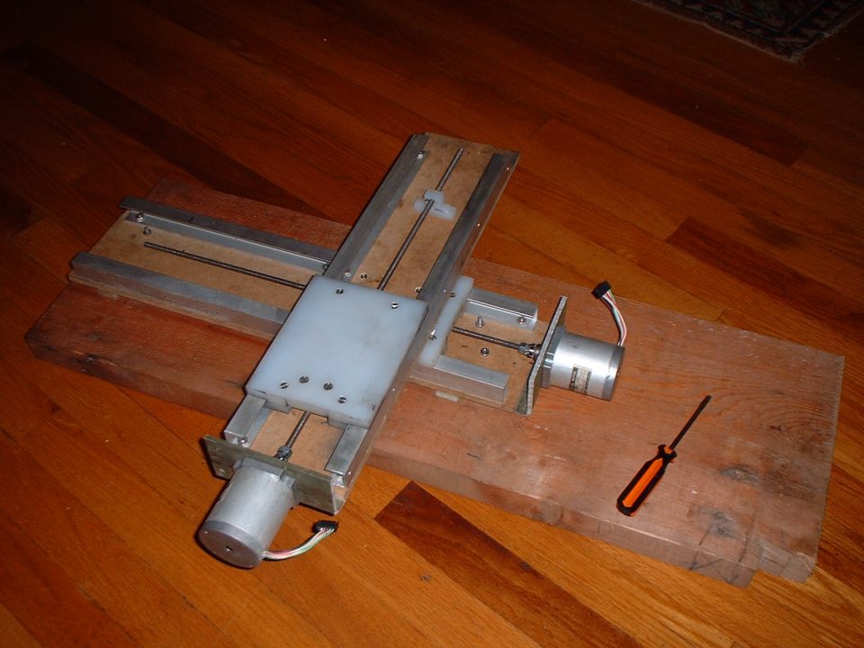 |
Another view back at the house... This thing is heavy already !! I have about 14" of Y movement and 12" of X movement. |
 |
Isn't it beautiful :) |
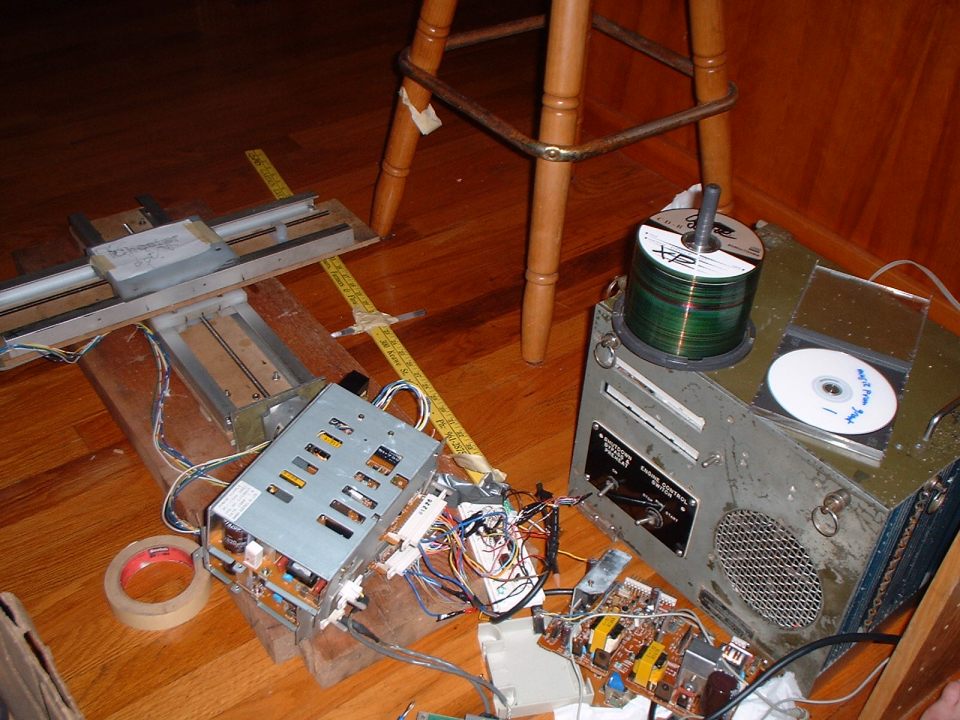 |
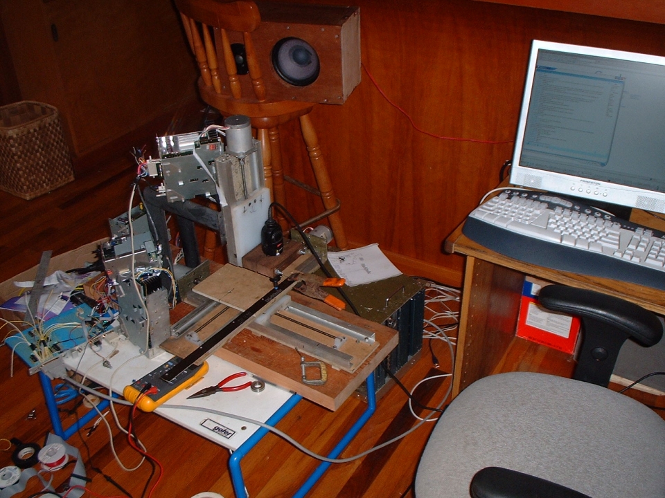
As soon as i was done with the X and Y axis I couldnt wait any longer to test this thing :). The metal boxes you see on the on the 1.5" by 12" are the 3A 25V drivers from the HP laserjet 2 printers. The little white breadboard next to them does the converting from direction/step signals into the 4 bit decoded step outputs. On the right of everything is my computer... With its custom aluminum case, severly in need of some engraving ;) |
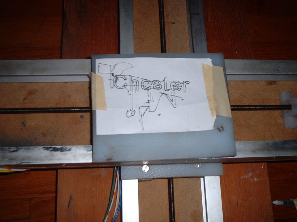 |
This was done with a pen suspended from a ruler... All the inaccuracy is from the pen movement. |
 |
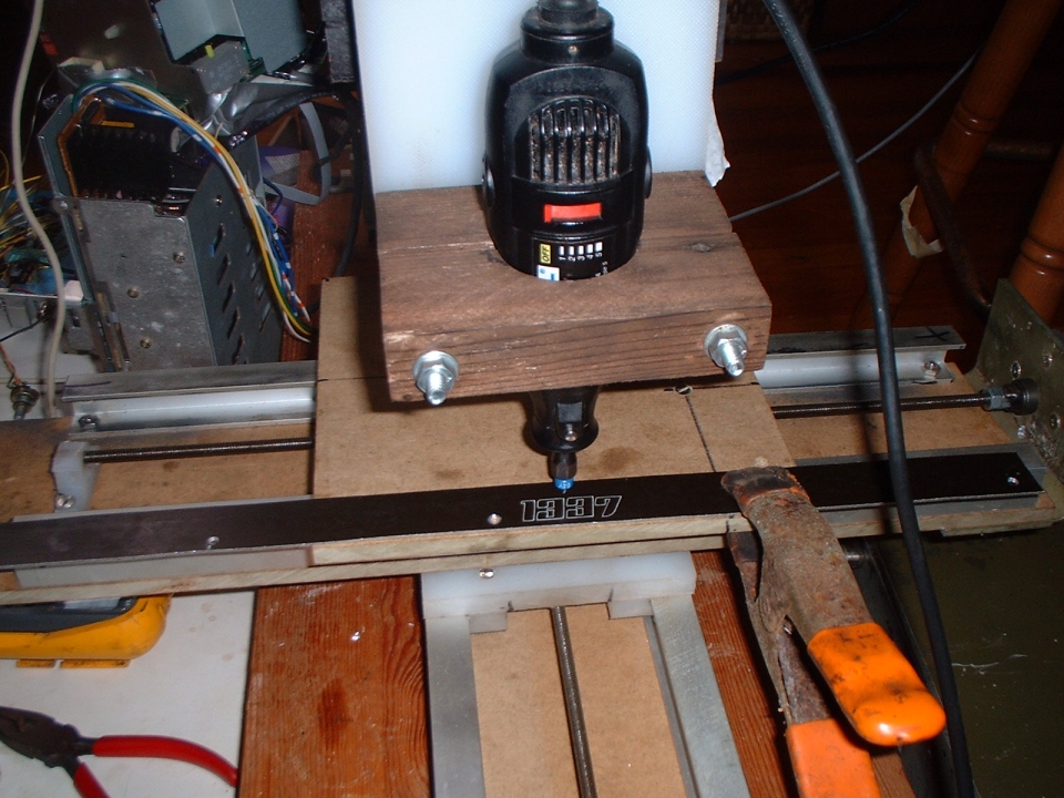
Thought id take some pictures while it was still looking semi new... |
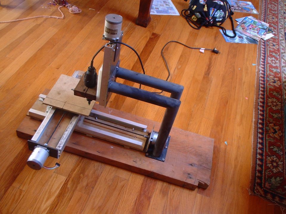 |
The Z axiz support is made from two pieces of 1.5" EMT (electrical metalic tubing) its just a thin wall steel tubing.. Welded to some plates for the top and bottom mounts. While I used 3/8" MDF (medium density fiberboard) for the X and Y ways, the Z axis was made from 3/16" aluminum plate, which is much more rigid and would have been a better choice for everything if I had enough... |
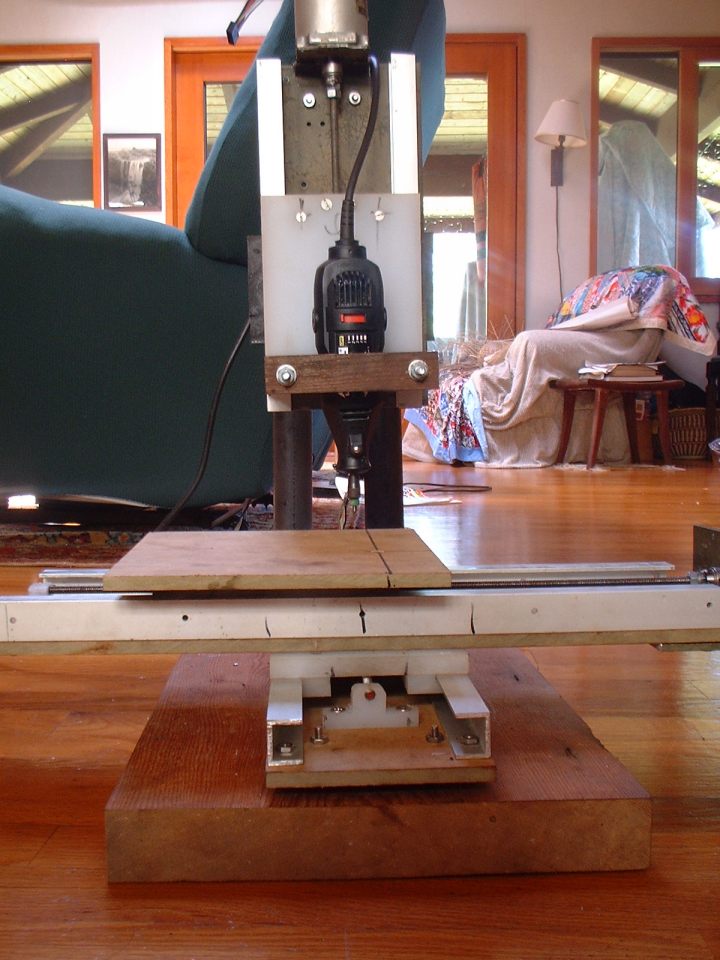 |
Front view, I really need to get a better table.. the fiberboard isnt very flat. |
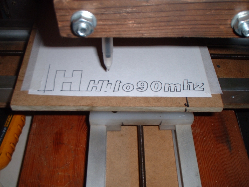 |
First drawing with the Z axis installed |
 |
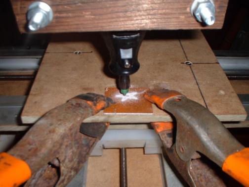
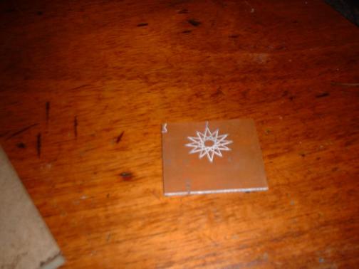
First engraving in metal !!!! boy was this fun. The metal is black anodized aluminum... Actually the same piece I started to build my first axis out of. |
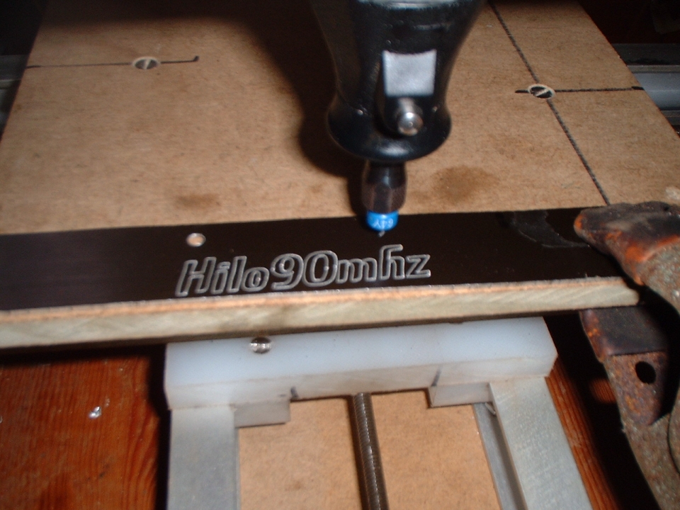 |
The obligatory hilo90mhz ;) |
 |
How everything looks right now.. I built a better controller board which is the blue thing on the left,
I was using a PIC16F628 for the X and Y before I had a Z but neeeded more output pins for 3 axises.. Its easy to change the JAL code to another micro, so thats what I did instead of just using two chips to get the other axis.. Here is the JAL source for PIC16F628 Here is the JAL source for PIC16F76 The code was compiled with JALcc and uses libraries that come with it. If there is much interest in the code I can make a simple schematic that shows how to hook it all up... The PIC16F628 code has the same pinout as THIS interpreter, just for a different chip. |
 |
First Successfull PCB Routing !!!! It took a few tries to find out how to make the tungsten carbide cutter bit on the diamond grinder... Now its working great making clean true cuts. |
 |
Sorry the picture is so bad... The board is only 1.5" x 1.5" and all the tiny copper triangles inbetween the lines are intact... Going to be fun once I have a real PCB design to etch onto a board. |
Software:
Mach2: Windows XP software with a good file converter and file preview, my mill doesnt seem to like the signal output that much.
TurboCNC: Great shareware DOS CNC software, basically all it does is interpret the G code files you already have... Theres no interference from other programs, i find it runs the best.
Links to other CNC mill pages:
hilo90mhz@hotmail.com