Chester's Propeller Clock
Analog/Digital
First off id like to give credit to all the people who have built propeller clocks before me and contributed to the information pool that is the internet. Inparticular I want to thank Don Zehnder for making manny improvements on his clock and putting information regarding it on the internet, because without it my clock would have never been possible.
All photos are clickable
Overview of what a propeller clock is and how it works:
Propeller clocks were to my knowledge first started by Bob Blick then many people started copying his idea and adding certain improvements along the way. Propclocks are really pretty complex devices, utilizing a PIC microcomputer that performs instructions at 10mhz. The PIC is the brain of the device and does most of the work involved in making the LEDs light up at just the right time so that it appears there are numbers, and in the analog mode hands suspened in mid air. On my version of the clock you change the mode and time setting while it is still spinning at about 1150 PRM. This is done through carefully alligned photo detectors and LEDs. These sensors are located on the rear of the spinning motor so they dont affect the look of the clock at all. (the below diagram should explain it)
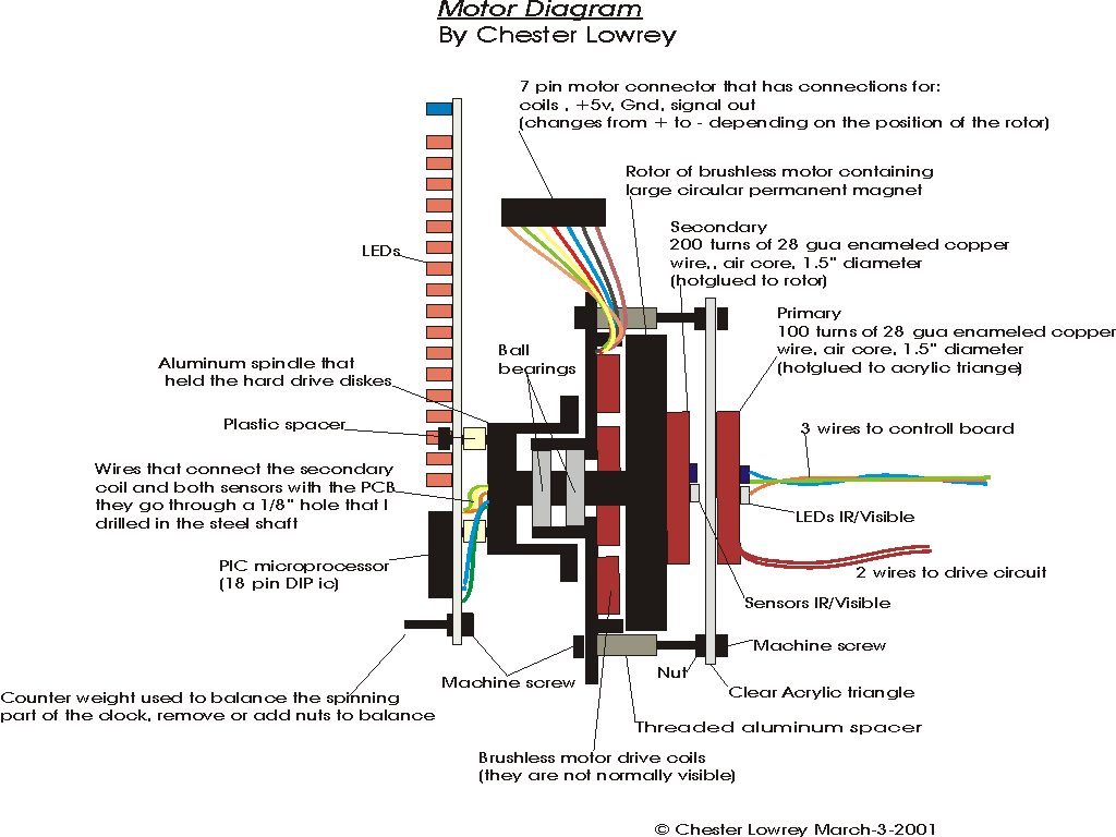
This is a link to the diagram i made, it shows how the whole thing works, and what makes my clock different from anyone elses i have seen sofar. (you better like that diagram cuz it took me about 5 hours to make :)
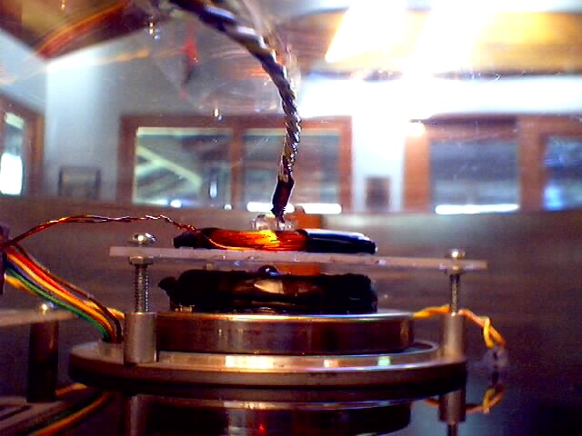
Here is an actuall photograph of the backside of the motor assembly. You can clearly see the standoffs and the acrylic stand for the coils and stuff, what you can also see in this picture is the secondary coil which is 200 turns of 28 gua copper wire, its the black thing wraped in electrical tape. Sticking our from the center of the secondary is the IR sensor which is used for changing the mode. The other sensor that is only sensitive to visible light was also mounted as close to the center of the spindle as possible with hot glue. Also the primary coil is located above it, i only wraped it in electrical tape in 3 spots because i thought this would improve cooling. It only gets slightly warm though so this probably wasnt needed.
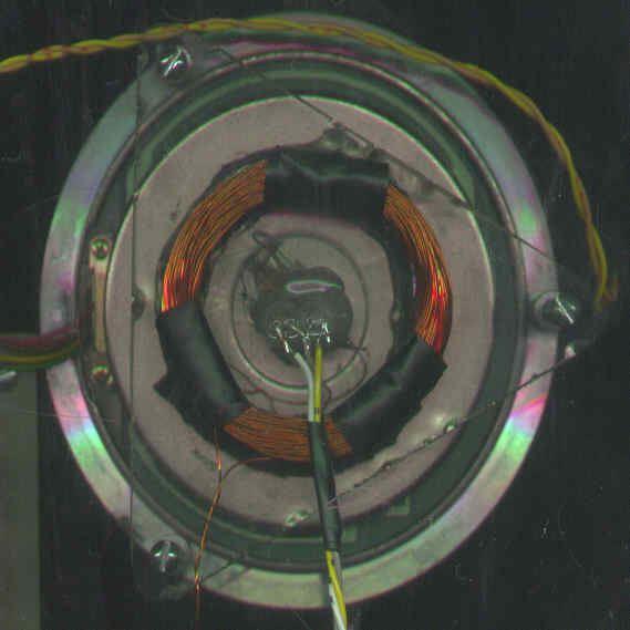
Here is a scann of the back of the clock, yess i actually layed the whole thing down on the bed of the scanner :). The barely visible acrylic triangle is spaced from the back of the motor with aluminum spacers, it has the primary of the drive coil hot glued to it, along with the IR led and red led used to change the mode and time settings of the clock while it is spinnning at around 1150 rpm.
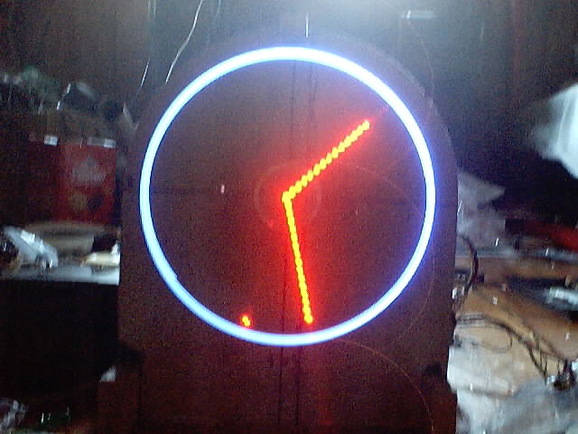
This is a digital photo of the front, i had to put white paper behind the clock because the camera wouldnt take good pictures of it with a black backdrop (the black acrylic sheet)
Here is the schematic of the clock and the rotating part of the transfomer. In my version of the clock the secondary of transformer, mode and time sensors were all located on the rear side of the motor. This diagram should help explain it all
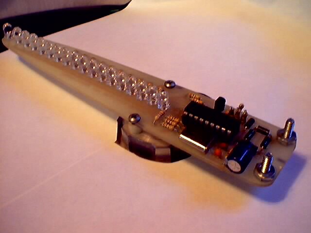
Here is the clock board layout showing the components and stuff, its mostly here to show where they go and stuff.
WANING!! this .pdf got screwed up and the holes are to close together when it is printed. I will try to fix this as soon as possible........... you can still view it and stuff, just dont try to make a pcb from it
Here is a link to the actual .pdf
file that i used to make my pcb, its 436kb but the quality isnt really the
best, but its as good as i could manage to get it !!! (I spent a very long
time fiddeling with the file just to get the quality this good !!)
If you would like to save the file so you wont have to dowload it twice just
right mouse click on the link and select "save target as"

Here is the schematic for the stationary part of the clock. It has a pulse width modulator circuit to controll the speed of the clock and a H bridge circuit to reverse the polarity of the signals going to the motor coils. It also has a seperate circuit for pulsing the main drive coil.
And here is the other circuit board for the clock, it controlls the brushelss DC motor and has a circuit to pulse the drive coil.
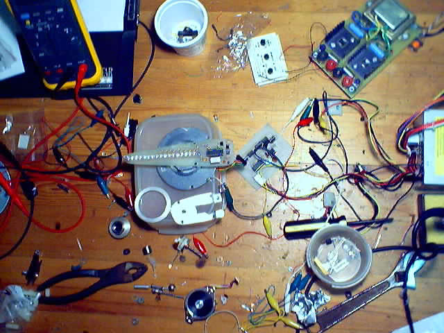
Here is a photo of construction of my first clock, yess i did build two. The first one was mostly a test to make sure that it would all work right, and to work out all the kinks there always are in new projects. This way when i built the second one i had the board almost unmodified unlike the first one which had components hanging off all over the place.
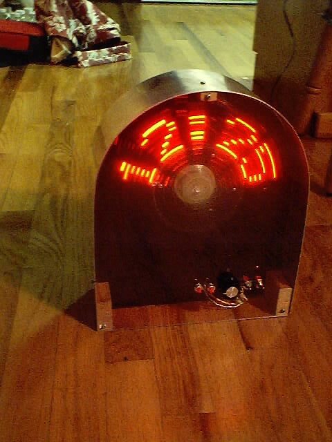
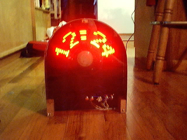
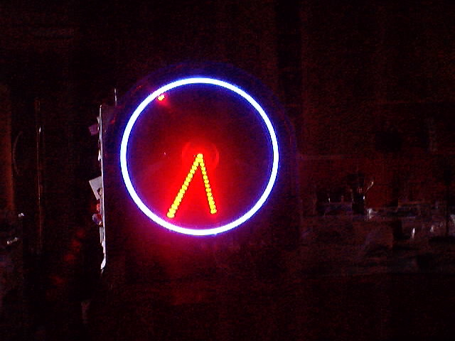
Photos of the operational clock !!

Email Chester Hilo90mhz@hotmail.com
Copyright © Chester Lowrey march 3 2001