SSTC 2

SSTC2 came into being during December 2003. Reason being I had too many IGBTs and too much time and I wanted to test a new method of building H bridges.
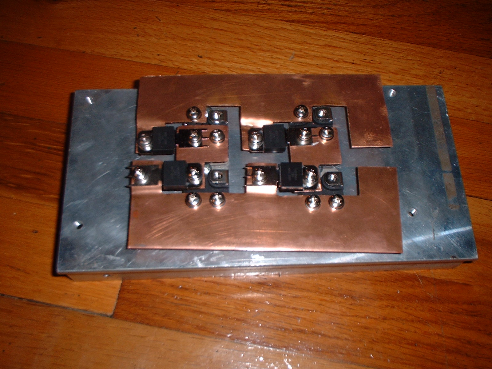

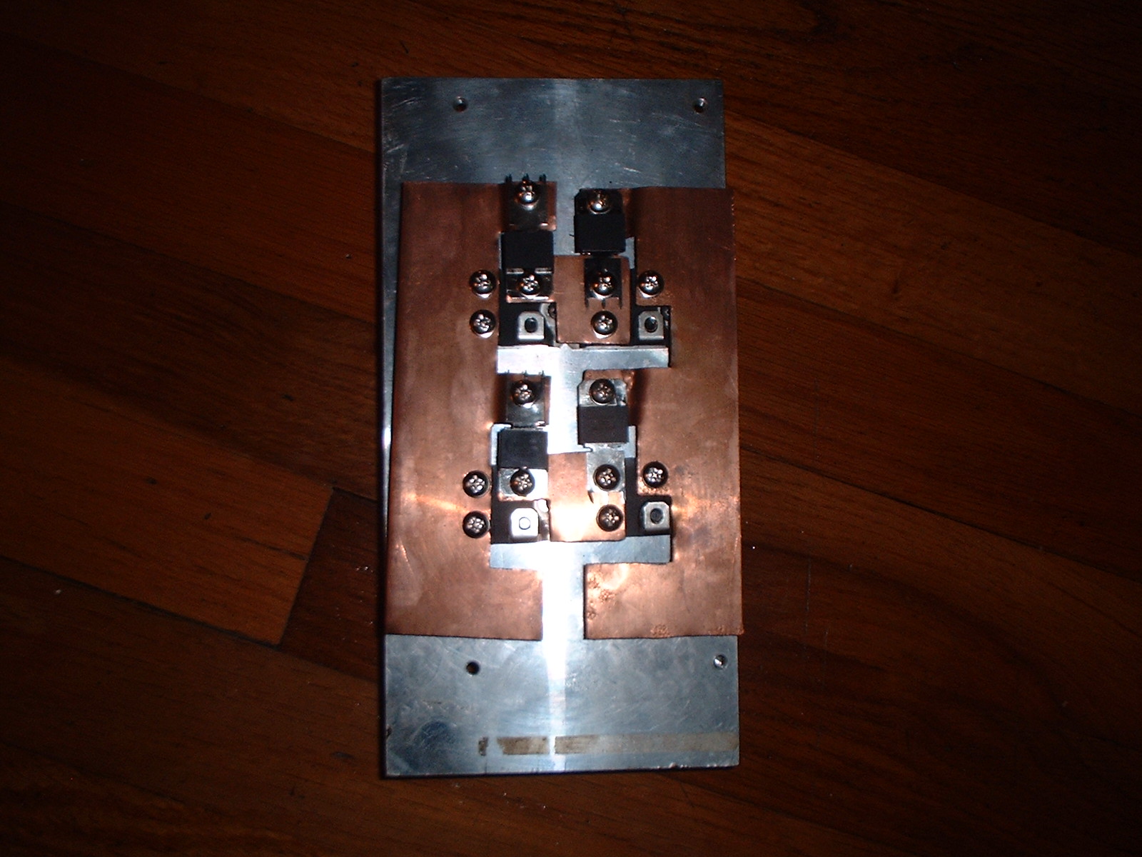
I believe the copper plate is 22 guage, the IGBTs are GA200SA60U - 600V 200A. Diodes are 400V 120A monsters.
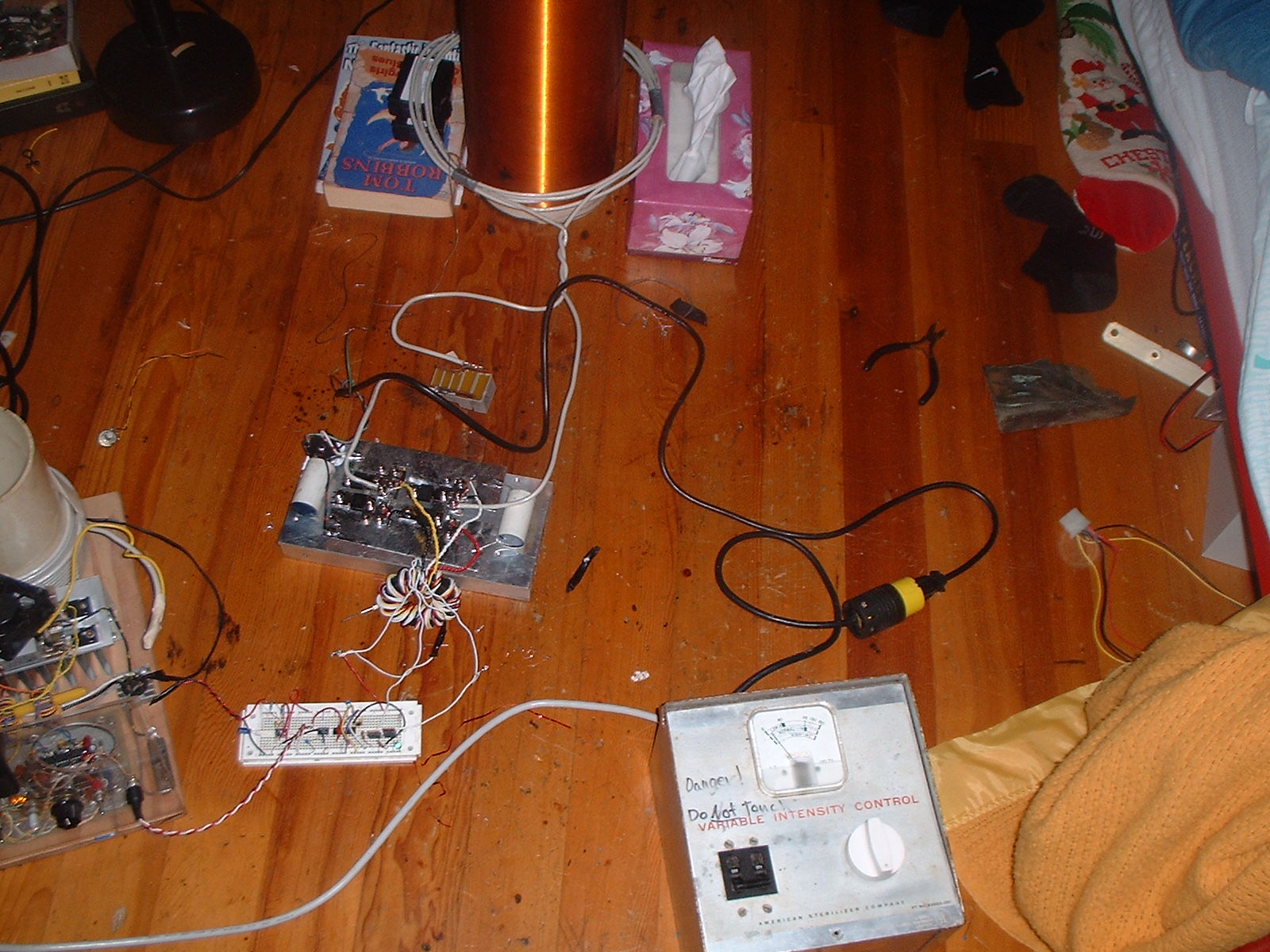
This is the basic test setup... I havent yet
made it into a real tesla coil, just a lashed together mess - which is always
fun.
The gate driver is all on the breadboard, with the drive signal
(oscillator) coming from my previous tesla coil via the signal out jack. There
is no feedback.
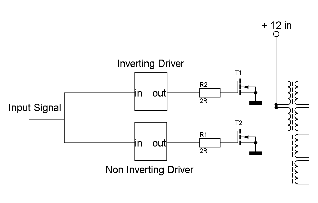
Very simple gate driver schematic, I used TI samples for the inverting and noninverting drivers.
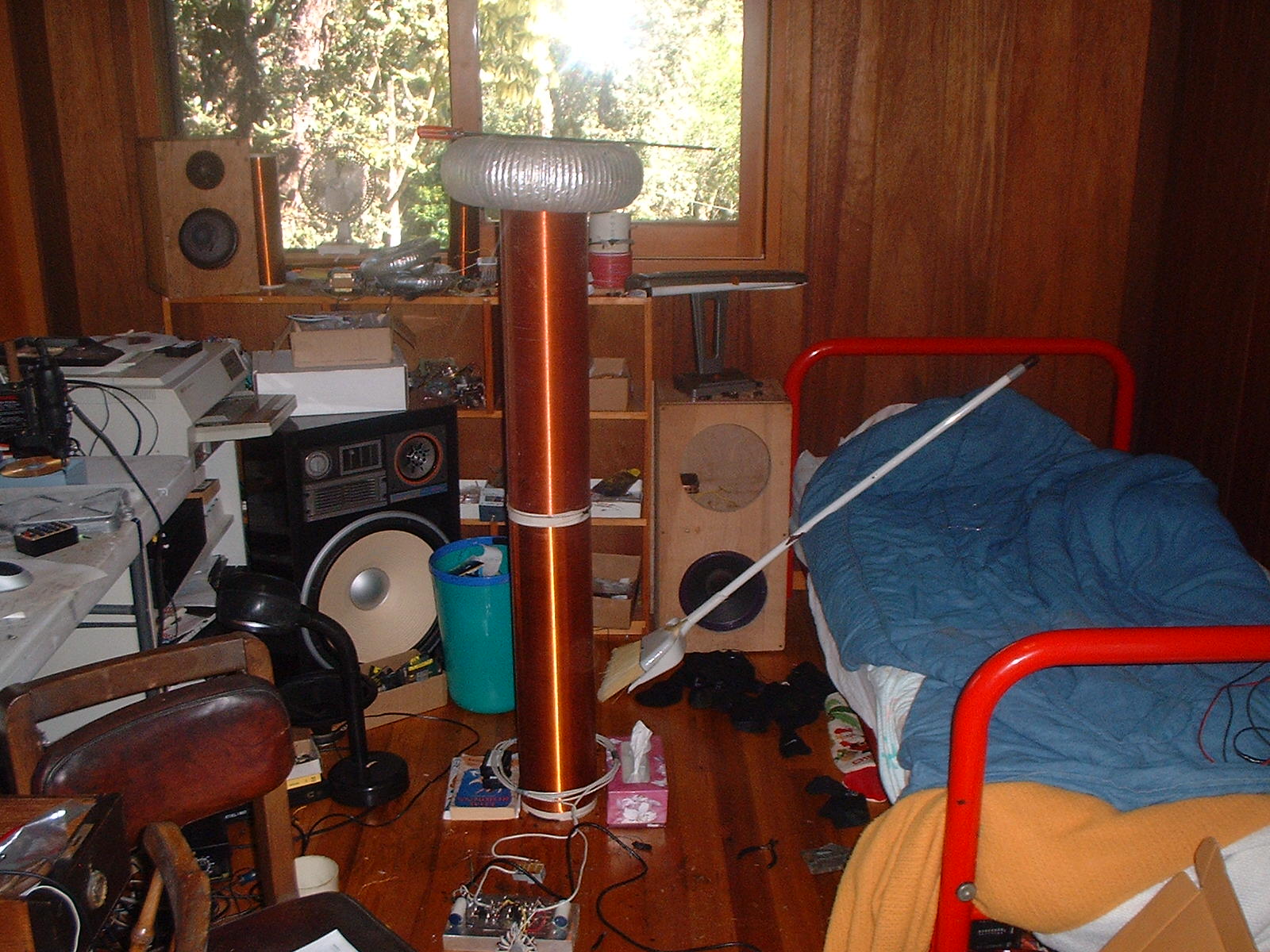
The Secondary is actually two secondaries stacked ontop of eachother... both 6" by 24" long, one wound with 28awg the other 24awg copper wire. With the topload it resonates at 170khz.
The topload is something like 4" diameter by 14" wide
Primary started out being 5 turns close wound like you can see in the pic... later on Ibuilt a better one with a real former. These first tests were done with 120v half wave rectified.
First Sparks.
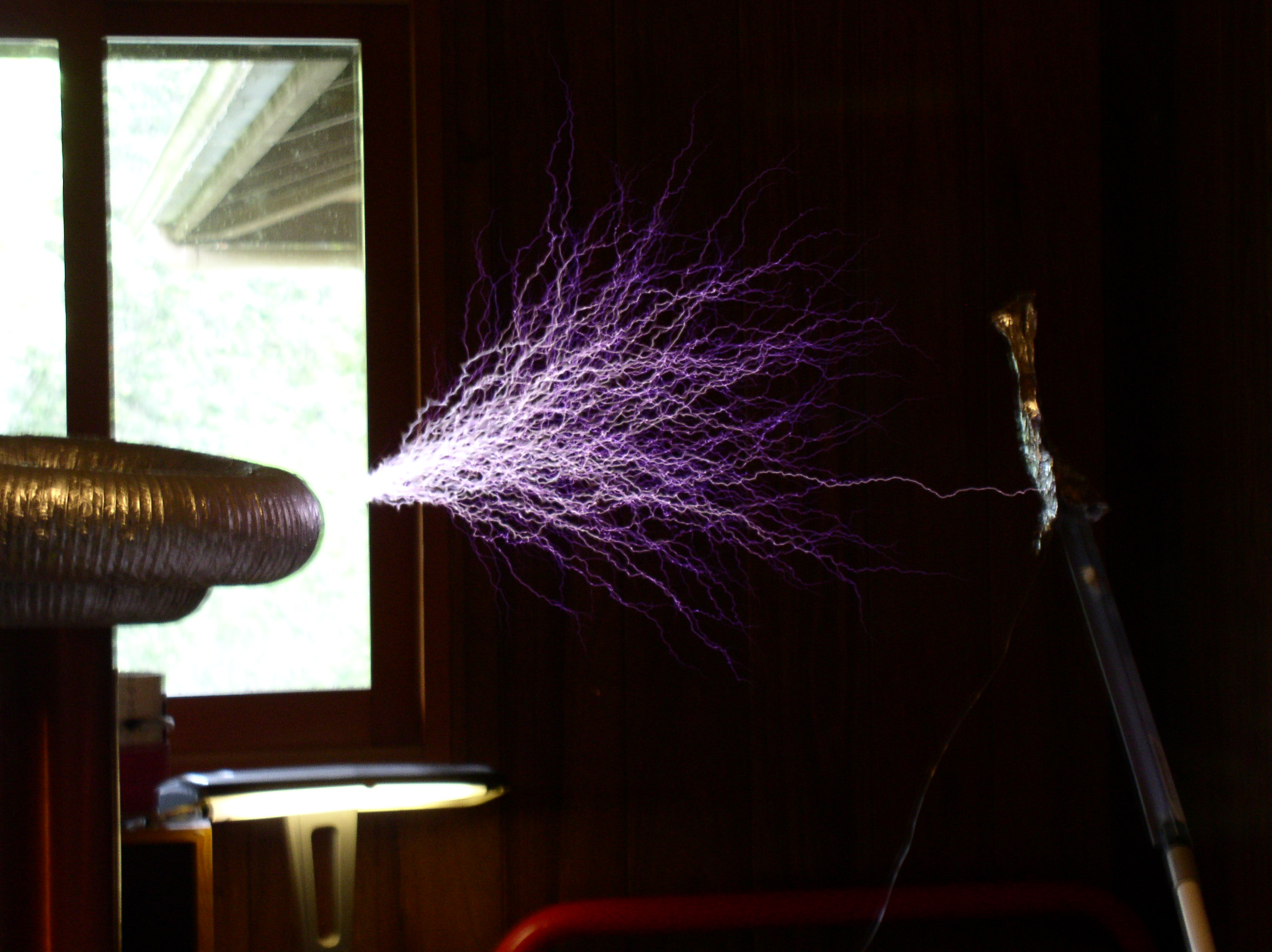
.62 second exposure I think the distance was about 29 inches.

1/60th second exposure.
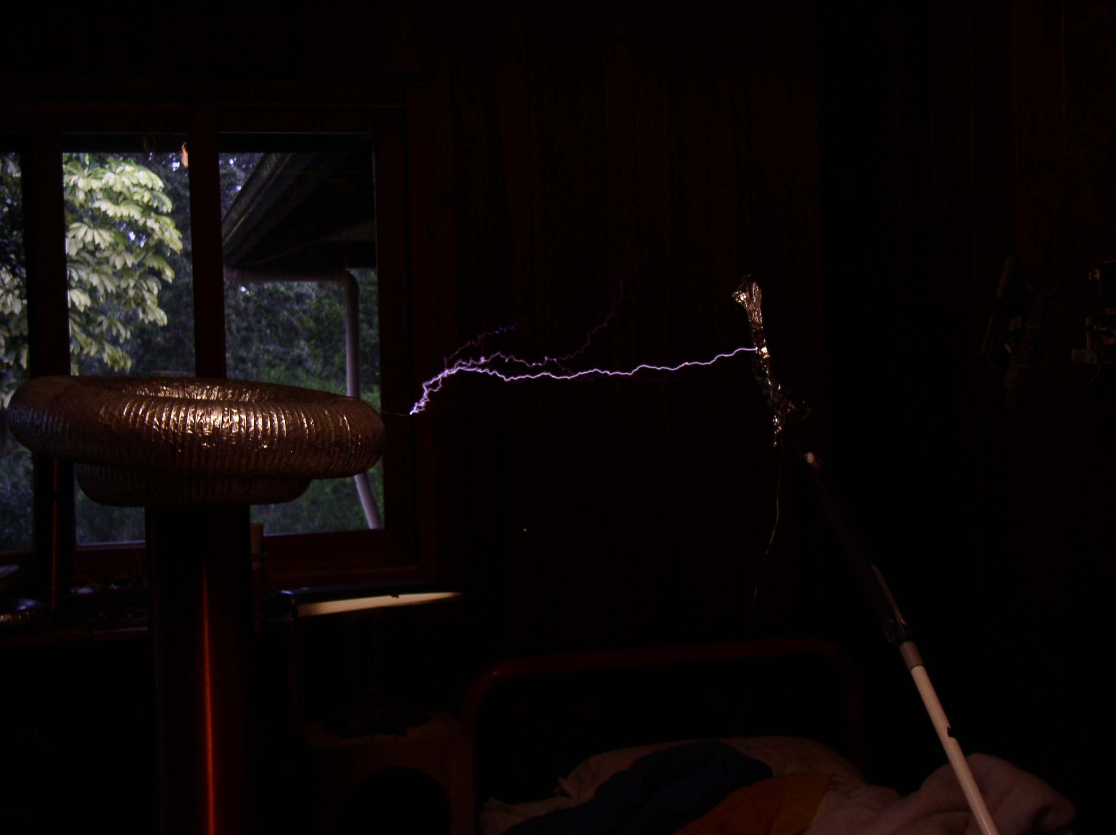
Same exposure time, slightly longer spark length
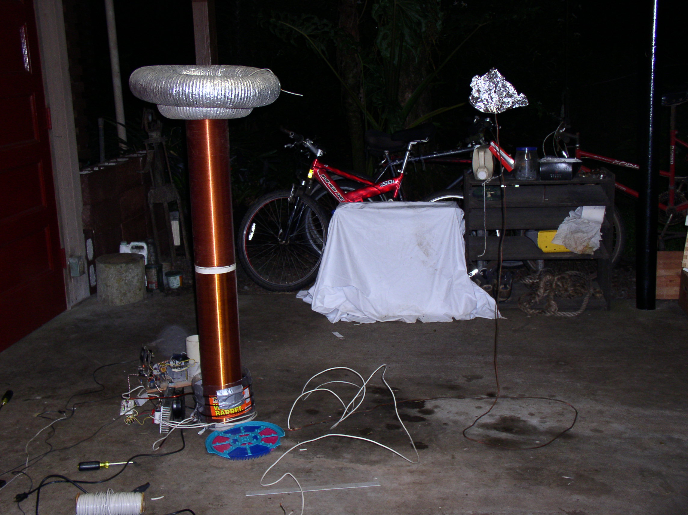
Then I decided I wanted more power... So i moved the coil into the garage and hooked it up to 240v.
I had problems with the circuit breaker blowing in this setup... First i was using an outside plug that didnt like the ground currents or something and shut off my IGBT driver while power was still being deliverd, I think thats the reason 2 IGBTs died.
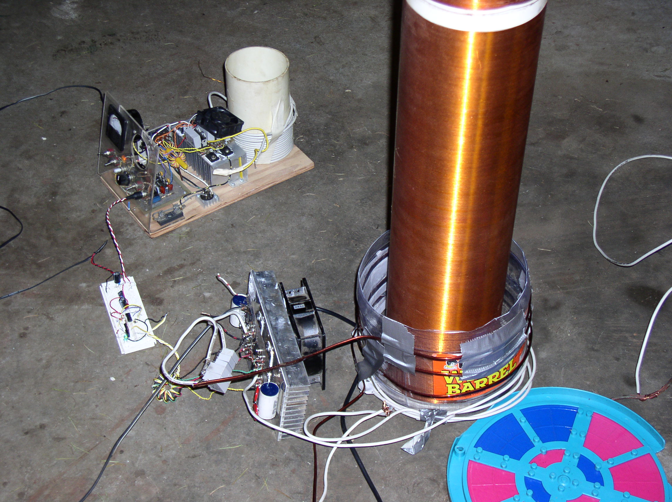
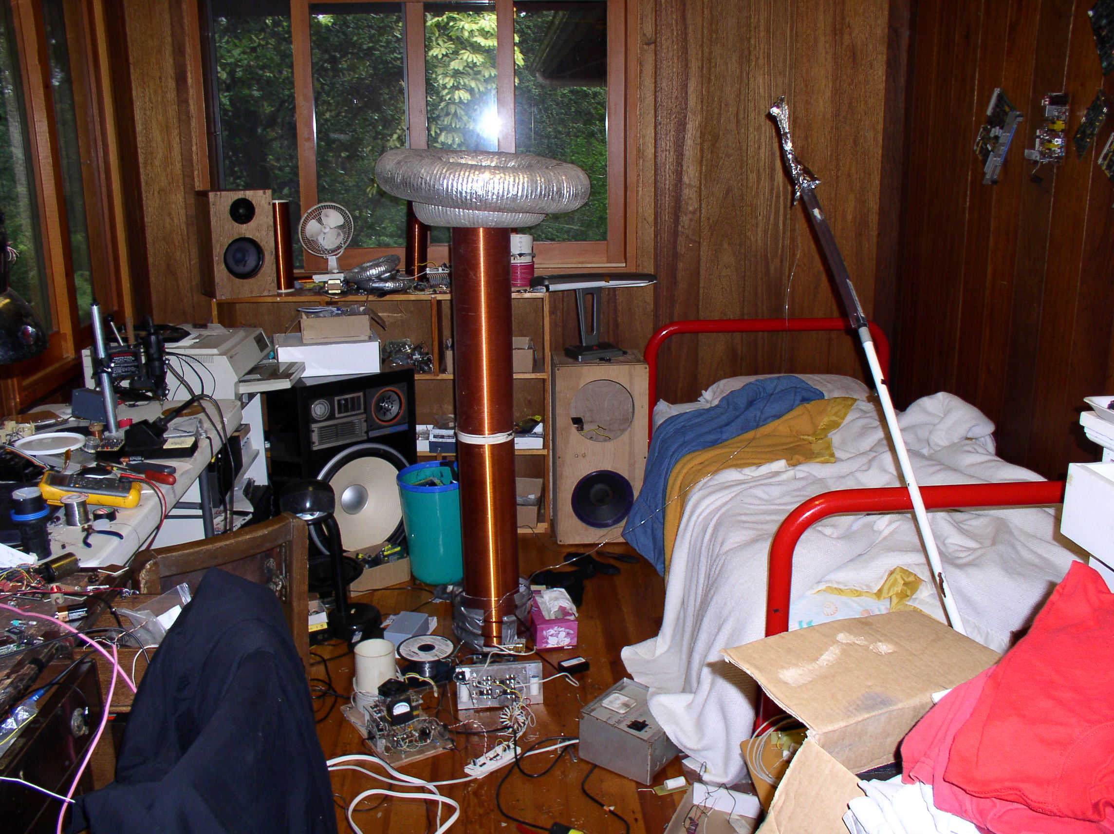
I also suspected that i needed more primary turns with the higher voltage so I sloppily added the 10awg wire you see below the primary former.
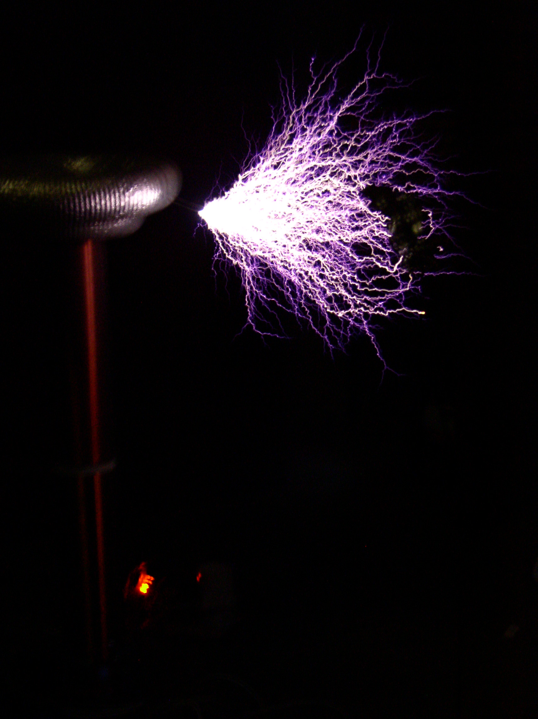
Here is the 1 second exposure my friend took before two more IGBTs blew :| I didnt feel like burning any more IGBTs in the current setup so thats where the project ended... As you can see the ground point is pretty close to the secondary and could have been moved much further away, so until I rebuild the whole thing we wont know what the max spark length is. The IGBTs were getting really hot in this configuration because of the hard switching, if i rebuild this setup ill use a feedback driver for soft switching.

Primary waveforms, one across each MOSFET

Gate waveforms on two opposing IGBTs