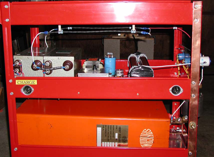
 Side View All pics are clickable |
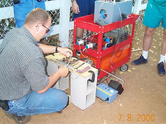
Getting set up at SoCal Teslathon 2000 |
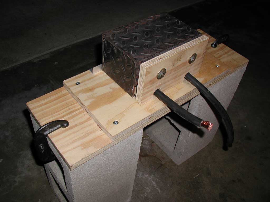 Containment |
This page shows the progress that I made on sucessive revision of the Pulse Discharge Machine
System 3
Side View All pics are clickable |
Getting set up at SoCal Teslathon 2000 |
Containment |
Here are a few photos of the the new
system integrated into a 3 shelf utility card. The first shelf houses my
tesla coil power controller that doubles as part of the control circuitry for
the pulse cap. The "aux" output serves as an ARM switch.
The bleeder resistors are removed from the capacitor only when the ARM signal
goes high (+120V). The "main" output serves as the CHARGE
switch. The HV PSU is simutaneously turned on and connected to the pulse
cap when the CHARGE signal goes high. The HV PSU is disconnected from the
pulse cap before the pnuematic FIRE command is sent to prevent any possible
damage to the HV PSU circuitry. The switching of the CHARGE and ARM high
voltage is done by a pair of high voltage vacuum contactors. See the section on
HV switches below.
Take a look at the the "side view" shown in the first picture. You will notice (2) 15/60 NSTs wired in parallel. They are connected to a full wave rectifier composed of 2 strings of (20) 1KV, 3A diodes soldered together in series. The electronics in front of the NSTs is simply a DC power supply and a pair of relays to allow 120V to control the 24V coils in the HV vac contactors. The 2 resistors are about 50K ohm each and are wired in parallel to serve as my bleeder resistors. They are always connected to the capacitor except when the ARM signal is high. Note the copper ground strap mounted to the side of the cart. This ensures that no part of the cart is ever hot with respect to ground - this is an essential safety measure!
Currently the lower section of the containment consists of several inches of plywood with a polycarbonate sheet mounted below the electrodes. The top of the containment is steel diamond plate. I'm having 2 problems with the containment. The first problem is that the exploding wire from quarter shots eats through the PC and wood in a matter of 10-20 shots. The explosive force of the supersonic wire shrapnel is amazing. The second problem was discover after noticing that I was having problems charging the cap all the way to 10KV. Close observation revealed that the damp wood and cinder blocks were acting as a resistor from the hot terminal of the cap to ground. On a quite night you could even hear the bottom of the cinder blocks "sizzle" against the concrete floor of the garage. The problem was temporarily solved by placing a sheet of PE under the blocks. A more elegant containment is in order... Another good idea would be to put the trigatron on the the "hot" side of the high current path versus the ground side. This makes for a safer rig but adds additional mechanical difficulty to my setup.
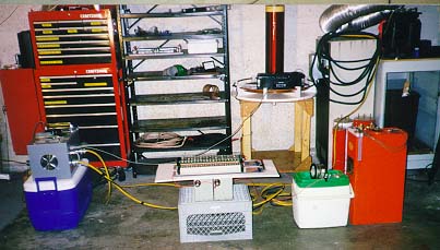
System 2
|
|
| This setup displays notable refinements. Among them are the trigatron, trigatron firing circuit with pneumatic switch, HV meter in a box, and better mounting of the NSTs and variac. Also note the homemade HV relay in the clear plastic container. We took a normal relay and submerged it in transformer oil. We routed the rectified HV DC through the relay to the cap. We wired the coil of the relay in parallel to the contactor in the tesla coil power controller so that it dropped out when I released the deadman. In theory, this will make life a lot easier on my rectifiers and everything else on the charging side should something go terribly wrong. Brain Basura, Bruce Basura, and Alan Yang are shown from right to left. System #3 is on the drawing board and will include everyting in one triple decker cart with heavy duty casters. |
|
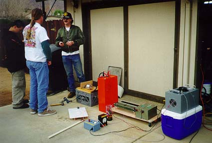
System 1
|
| Brian can over one day and said, "Hey, why don't we hook up that old pulse cap?" Sounded good to me so we went out to the garage and started wiring. This is what we arrived at about 2 hours later. The tesla coil power controller is shown on top of the cooler. There are 2 paralleled NSTs on top of the milk crate. Above them are 2 recitfier stacks that feed the pulse cap through 11K of resistance. The 10KV meter is shown on top of the green and white cooler. The pulse cap is obvious. Note the hi-tech EMP tester (radio) resting on the tesla coil primary. It was included to see if enough RF could be produced during the various experiments to kill simple RF receivers. It lived - this time... |