Opto-Isolated Current and Voltage Monitoring for High Voltage Applications
History
Terry Fritz began this project back in 1998. He needed a means of
measuring voltage and current waveforms of the Tesla Coil primary circuit while
protecting his expensive test equipment. The project has undergone 4 major
revisions and although it will always be a work in progress, it has reached a
level of refinement that makes it a reliable piece of HV test equipment with a
bandwidth of up to 40 mhz. All of the design work presented here was done
by Terry Fritz and may be found at his site of http://hot-streamer.com/TeslaCoils/Misc/.
I've merely gathered the latest project information in one place and added info
that I've found useful in the construction and operation of the Fritz
Fiberprobes.
Theory and Operation
Probe Operation and Calibration by Terry Fritz (MS Word) (I can provide alternate format if necessary)
Additional
Info by Ross Overstreet
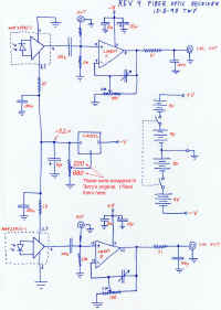
- fixed the voltage regular resistors that were swapped on original receiver
schematic
- discovered that vasoline failed as a dielectric on the 50KV transducer
after about 20 sec of run time across a 15/60 NST
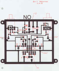
- mechanical stress on the receiver PCB seems to dramatically effect the
accuracy of the waveform
- using panel mount receiver detectors instead of bayonet mount will help
the above problem and simplify mounting
- I suspect that both channels of the fiber cable don't have the same
attenuation. We must always use the same fiber with the same
channels
Parts List
Probe Parts List by Terry Fritz (MS Excel) (I can provide alternate format if necessary)
Schematics
Receiver
Transmitter
Transducer Schematic
Pictures of the components
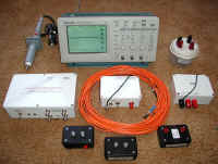 Overview of fiberprobe components. |
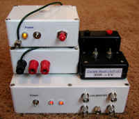 Close-Up of Receiver, Transmitters, and a 2 of the current transducers |
Other High Voltage Instrumentation
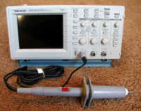
This is a nifty 1000:1 RF Voltage probe with a bandwidth of 5
mhz.
It will allow me to safely probe voltages up to 15 KV(peak)