|
|
|
|
|
|
|
Tesla Coil Measurements & Misc Stuff
This section is designed to instruct the beginner in using basic test equipment to gain further insight into the nature of Tesla Coils.
SECONDARY
RESONANT FREQUENCY
PRIMARY
RESONANT FREQUENCY
Q
(with comments from Malcolm Watts))
Q = F(r) / ( F(hi) - F(lo) )
Fr = resonant freq in Hz
F(hi) = upper freq where amplitude decreases to 70% of amplitude of F(r)
F(lo) = lower freq where amplitude decreases to 70% of amplitude of F(r)
Malcolm: Important: the signal source must have as low an impedance as possible as generator ESR adds to coil ESR and will lower the actual Q figure. Also, it is important that the scope probe/aerial be positioned as far away as possible in order not to load thesecondary as this will degrade the figure also. Not a major concern for a casual measurement but matters a lot if you are comparing different resonators.
COUPLING
(cut from TCML post on 11/27/97 by Terry Fritz)
Apply a heavy 60 Hz AC current to the primary coil. This is best
done by placing a space heater, hair dryer, etc. in series with the primary
to limit the current to about 10 amps. Measure this current with a
multimeter. Note that the space heater gives a fairly stable resistance.
Light bulbs have a non-linear resistance through the AC cycle and distort
the measurement (they must cool down substantially at the nodes of the AC
cycle). Of course, use great caution with the live AC on the primary so as
not to kill yourself. Only the isolated primary need be connected to the AC.
The capacitors, transformers, and other wiring should be disconnected from
the primary for this test. Be cautious of the AC finding its way on to the
secondary!
Place a 10k ohm resistor and a 1uF capacitor across the secondary and
measure the AC voltage. It will be on the order of say 100 mV AC. The
resistor and capacitor will eliminate stray noise picked up by the secondary
and swamp any resonance which is significant at these low levels.
Coupling is defined as:
K = M / sqrt(L1 * L2)
M = Mutual Inductance in Henries
L1 = inductance of primary in Henries
L2 = inductance of secondary in Henries
The mutual inductance is found by:
M = V / (w * I)
V = The measured secondary voltage in volts AC.
w = the line frequency in radians per second (377 for 60Hz or 314 for 50 Hz).
I = The measured current in the primary in amps AC.
TEXT FILES: Collection of interesting posts to either the HV list or Tesla List
A real electrocution (MS Word format) - I ripped this off of a site without permission, but I didn't want to lose it.
COMPUTER PROGRAMS:
Computer based tools have revolutionized the design of Telsa Coils.
The
following links and files contain the most commonly used programs in the Tesla
community.
Ross Overstreet's QTC Excel
Spreadsheet
My tool of choice! This is a revision of Corey
Ruch's revision of Ed Sonderman's
original TC calculator spreadsheet. Each version has different
things that the programmer felt was important or reflected the individual's
style. My version is mostly consists of a GUI change that uses less
screen space for the same info. I also cleaned up some of the
equations. The spreadsheet programs are my favorite because they are
so easy to modify to suit your individual taste or needs. The program
is designed with the intermediate coiler in mind so people not familiar with
basic TC theory may have a few questions. Since the equations in QTC
are based on empiracle data the accuracy is limited to about +/-10%
(although it usually does better than this).
Link
to Terry Fritz's E-Tesla Program
Terry wrote and incredible program that uses nothing but coil geometry, coil
inductance, and Maxwell's eqns to calculate a coils resonant freq to within
1%! There is a C and Q basic verion available.
MAGAZINE
/ BOOK ARTICLES:
Malcolm Watt's
Wireless World
Article
|
|
|
|
|
|
|
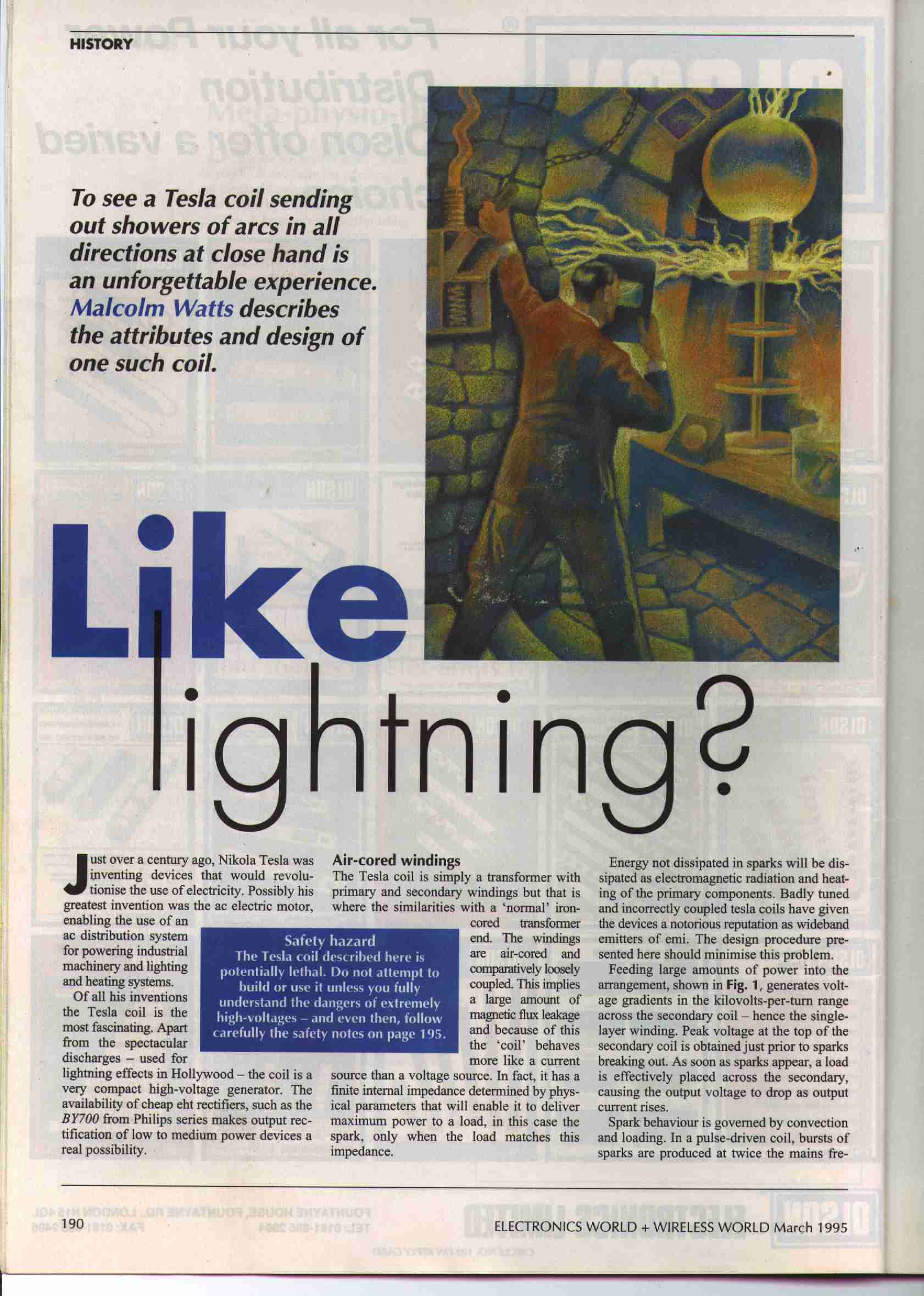
This article appeared in the March 1995
issue of Electronics World + Wireless World. It describe sthe
construction and tuning of a simple table-top TC. The article provides
great insight into using an oscilloscope and signal generator to tune a coil.
Terry Fritz originally scanned this
article and placed it on his site. I downloaded it, got Malcolm's
permission, and reposted it here. Malcolm asked me to append the following
notes to the article.
Malcolm Watts
[malcolm.watts@wnp.ac.nz]:
Please also be aware that the equation for output voltage in the article does
not apply to disruptive coils. I posted a note on this in "Letters to the
Editor" in a subsequent edition (around August '95 I think it was. Also,
like so many others floating out there, the terminal capacitance equation is
only correct for a very limited set of circumstances and is therefore invalid in
the strict logical sense. It won't work for some coils.