My first solid state TC (AC output)
using a television fly-back transformer
(output peak voltage up to 8.1kV)
Table of contents:
|
||
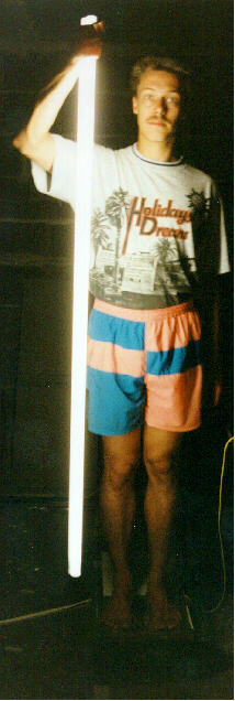
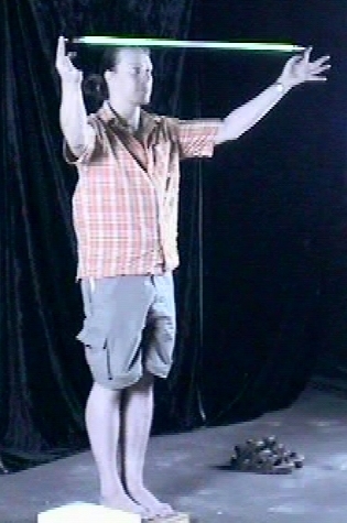
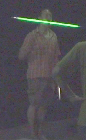
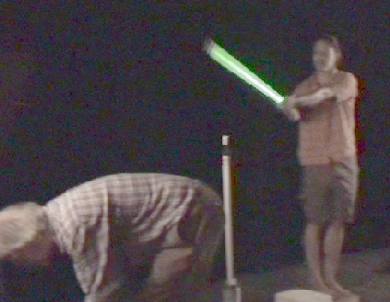
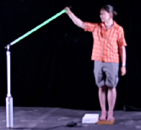
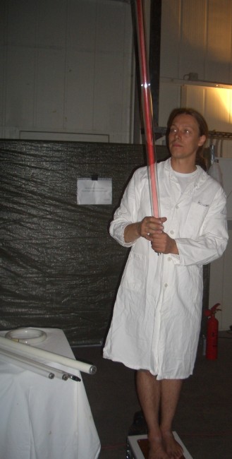
Me standing on the isolated HV-electrode, |
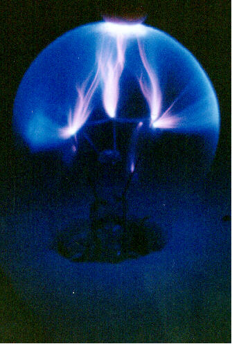
Plasmaglobe, made from a |


In September 2005 I tested the circuit with increased the input voltage (up to 20V). This definately requires a bigger heatsink for runtimes more than a few seconds. I also removed one of the transistors to get the same circuit Sam has. The high voltage output dropped both in voltage and power compared to the old circuit with two transistors. So I'll stick with the old circuit.
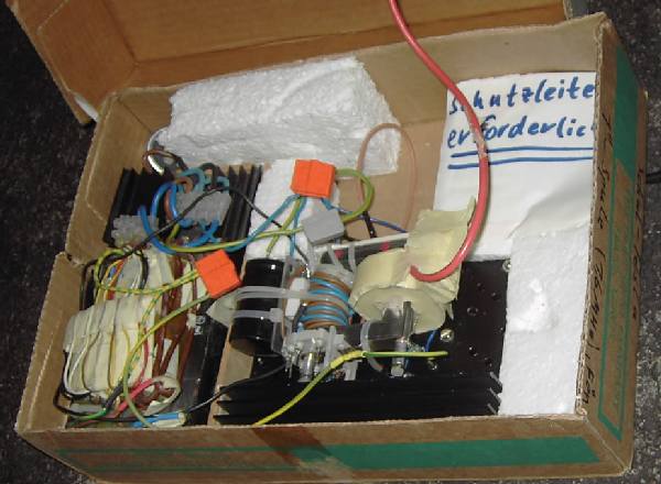
The old circuit was "housed" in a cardbox (actually just thrown in ;-) with the copper plate (to stand on) screwed to the (originally) bottom of an upside down placed wooden drawer. I decided to build the thing into an alumnium attache case so that I can simply stand on the case during the performance. Since I moved to >20V, I now use two lead acid batteries for powering the whole thing including the two fans for active cooling of the big heatsink mounted in the case. I also added a rubber bulb with pressure switch, so I can switch it on now with my foot. Much safer and more comfortable than before. And it looks much better of course.
The new circuit will be:
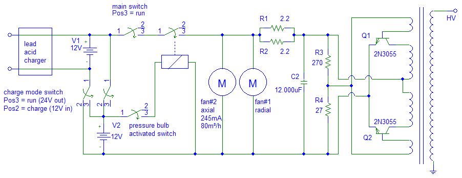
For charging the lead acid batteries, the left switch (charge mode
switch) has to be brought up into the upper position.
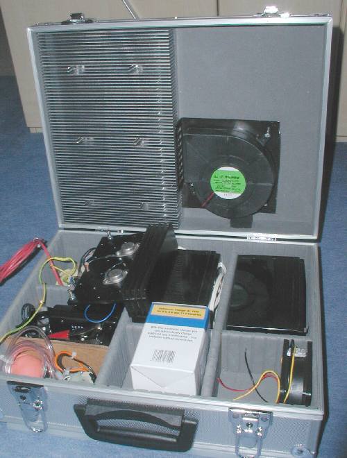
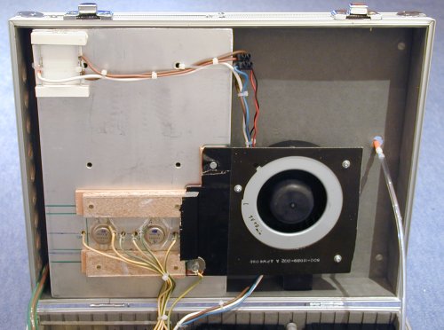
This is the new housing. The alumnium heat sink will be mounted the other
way round with the flat side down for easy mounting of the transistors. Outlet
for the hot air will be on the left side of course. The axial fan in the
bottom part of the case on the right side will help pumping more air through
the case and cool the outer fins which are not blown directly by the radial
fan. You can see the transistors still sitting on the old (too small)
heatsink.
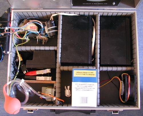
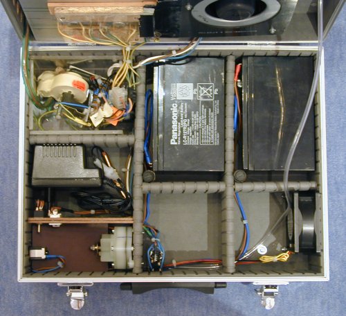
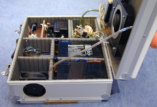
Here you can see the two lead acid batteries on the top right side, the flyback
on the top left side, the pressure switch on the botom left side and the
charger in the middle of the left side. Eventually the cardbox in the middle
at the bottom side will be replaced by a block of wood so that I can stand
on the case during the performance though the thick PE-board on the top cover
makes it very stable.
The box is now finished and the circuit still working ;-)
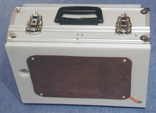
The following image shows the bottom of the alumnium case. I backed it up with a PE-board so that it not only stands on the 4 feet in the corners but on the whole side. To make contact with the concrete floor (grounding as a counterpoise to me standing on top of the case), I added a piece of brass sheet. Eventually, I'll remove the 4 feet and the PE-board in the future.
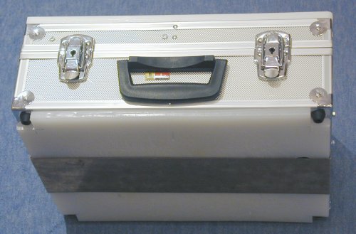
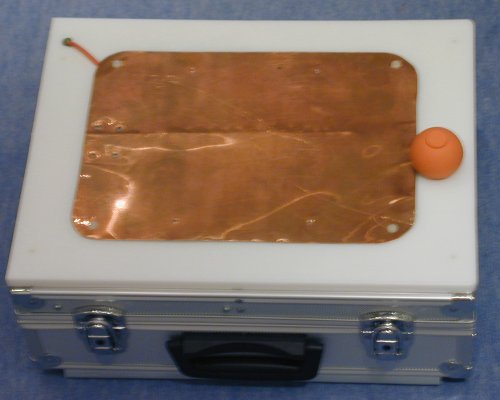
The next two images show the top side of the case. A PE-board isolates the copper plate from the case (case is the circuits ground, I'll stand on the copper plate). To switch the circuit on, I just have to press the rubber bulb with my toe ;-)
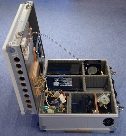
A view inside the box:
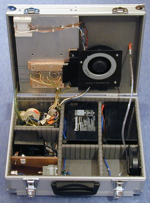
For charging the lead acid batteries, the left switch has to be brought up
into the upper position.
The top and bottom part in more detail:
The next two images show the air inlet on the right side of the case in the bottom part and the many air outlets on the left side in the top part. You also can see the connector (socket) for charging the lead acid batteries in the bottom part of the case in the second image:
I measured the peak output voltage (open circuit) with
this circuit:
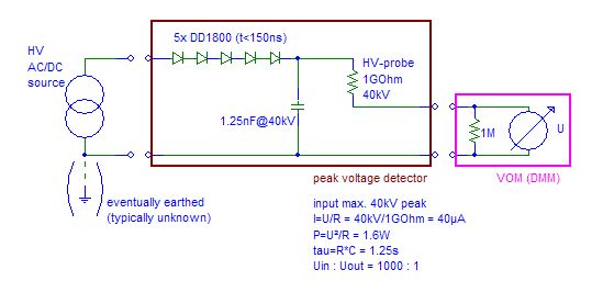
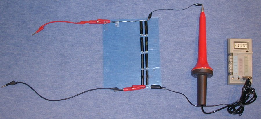
Surprisingly, it was quite low compared to the appearance of the arc, only 6.6kV peak (Ueff~4.7kV, Uss=13.2kV).
I suspected that the copper plate on top of the case was acting as a capacitive load to the circuit. So I disconnected the copper plate and measured 8.1kV peak (Ueff~5.8kV, Uss=16.2kV).
I still have to perform some measurements:
input power
output current (closed circuit)
output voltage (with me standing on the box)
output current (with me standing on the box)
< new circuit data coming soon >
Since the caps I have for this (120pcs. 3nF 30kV) are not designed for pulse discharges, I have to use a current limiter on the output side (see Jochens HV-pages for details).
Diodes to be used are either KYX28/15 (15kV/2mA) like here http://www.rapp-instruments.de/diverse/multiplier2/multiplier.htm or Diotecs DD1800 (18kV/20mA) http://diotec.com/pdf/dd300.pdf.
< new circuit data coming soon >
![]()
I'll make a separate page on the Cascade as soon as there is more than some parts and plans.

![]()
![]()