An Experiment to Determine the Output Power Capability of
Current Limited Neon Sign Transformers.
Terry Fritz
January 14, 2003
Background
The use of a simple Neon Sign Transformer (NST) for high voltage power uses has been discussed recently by Richard Hull in his paper "High Voltage Power Transformers for the Researcher An Investigation of the Neon Sign Transformer" 1 . In this excellent paper, Hull describes his experiments regarding the load vs. power characteristics of typical NSTs. He concludes, that as the transformer is loaded down, the output voltage drops sharply. This limits the usefulness of NSTs for high voltage power supply purposes.
However, Tesla coils operating the resonant and LTR (Larger than Resonant) 2 modes commonly draw the full VA rating from NSTs (and sometimes more). Thus, the question comes up if the same principles used to "extract" power out of NSTs in Tesla coils could be applied to simple high voltage power supply applications.
Discussion
Tesla coils use resonant AC charging effects 2 to basically bypass the current limiting ability of NSTs. For a power supply application, the load would likely have to be constant and basically resistive. While "wild" reactive loads are possible and certainly demonstrated in the case of Tesla coils, the design of such systems can be very complex. For the matter at hand, we shall simply attempt to demonstrate the basic principle and leave complex adaptations to the future.
Experiment
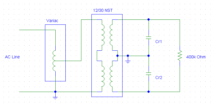
I would propose the following system to supply 12000 volts ACrms at 30mA to a 400k Ohm resistor using a 12000V/30mA NST. This is basically identical to the setup Richard Hull used, but with the addition of resonant capacitors Cr1 and Cr2. The selection of the values of the capacitors can be complex. 3 However, we will try using the simple 60Hz resonant formula:
Xr = 1 / (2 x pi x f x C)
C = 1 / (2 x pi x f x (Vnst / Inst)) == 6.63nF
Resonant Charging Setup
For this experiment, I will also add fusing and the usual high voltage metering and current measuring devices. I will also add a high voltage spark gap across the NST's output terminal as a safety device incase the experiment goes "bad". Since this is a resonant circuit, if the load is lost, the voltage on the output of the NST can skyrocket to perhaps 70,000 volts! A significant "detail" in such a power supply circuit!
The following setup was used to test the system.
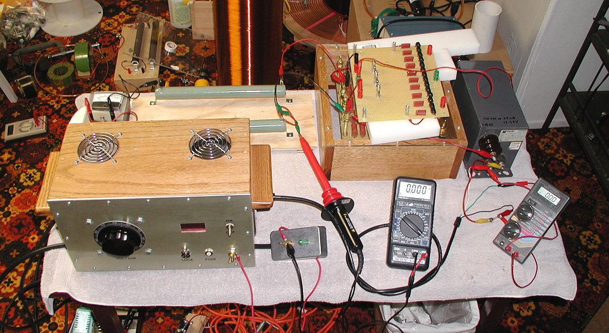
Test Setup
Results
The transformer resistors and various parts of the setup were verified to be sure they were working properly. One high voltage resistor was open and needed to be replaced. The transformer was found to produce 12.48kV at 29.0mA. The resistance was 386kOhm.
Three capacitance values were tested in the range of interest. With the following results:
Cr1 = Cr2 = 6.2nF
Vin (Vac) Vout(kVac) Iout (mAac)
25.7 2.0 4
51.3 4.0 10
76.4 6.0 15
101.8 8.0 21
126.9 10.0 26
Cr1 = Cr2 = 7nF
Vin (Vac) Vout(kVac) Iout (mAac)
25.4 2.0 4
50.5 4.0 10
75.0 6.0 15
99.6 8.0 20
124.0 10.0 26
Cr1 = Cr2 = 8nF
Vin (Vac) Vout(kVac) Iout (mAac)
24.9 2.0 4
49 4.0 10
73.9 6.0 15
98.3 8.0 20
122.1 10.0 26
The last result is typical and shows an output of 10.0kV at 26mA or 260 watts. The relationship between input and output voltage was linear.
Discussion
If we look at the transformer's output impedance as tested (12.48/29 = 430.34kOhm) and the 386kOhm resistance of the load, we could expect the output voltage to drop to 11.34kV which does not explain the rather lower than expected voltage. Also, the low current does not indicate excessive loading. Also, note that the output was surprisingly insensitive to changes in the resonant capacitance value.
Although the full 360VA output power of the NST was not reached, the transformer with resonant capacitors added to the output does show very stable and predictable output voltages and currents. This is perhaps useful in a number of high voltage power supply applications. It is interesting to note that the obtained 260Va is 72% of the transformers rated VA. Close to Richard Hull's “two thirds” rule.
Conclusion
The output VA was only 72% of the rated NST VA (260/360), Closely matching the “two thirds” rule. However, the characteristics of the NST were far more linear than in the case of a non-resonant capacitor system. In some cases, adding resonant capacitors may allow the use of NSTs as high voltage power supplies if the load is stable and always in circuit. Note that if the load is lost, the output voltage will skyrocket until something blows (perhaps 70kV!!).
1. "High Voltage Power Transformers for the Researcher An Investigation of the Neon Sign Transformer" Richard Hull
http://fusor.net/board/view.php?bn=fusor_files&key=1041985032
2. "AC resonant Charging" Richie Burnett
http://www.richieburnett.co.uk/resonant.html#resonant
3. " A method to determine the Linear Transformer Model parameters of a Neon Sign Transformer" Tero Ranta
http://hot-streamer.com/TeslaCoils/OtherPapers/TeroRanta/
NSTCapMatching/ResonantCapacitorMatch.htm
"A method to determine the Resonant Capacitor Value of an NST operated Tesla Coil" Tero Ranta
http://hot-streamer.com/TeslaCoils/OtherPapers/TeroRanta/
NSTCapMatching/ResonantCapacitorMatch.htm