4-2-2000 Terry Fritz
Parts needed:
Quantity Part Number Description Cost
1 RS# 42-3048 Mini-Strobe Light 34.99
1 RS# 270-1064 2 amp Slow blow Fuse 1.99/4
1 RS# 271-0120 8 Ohm 20 Watt Power Resistor 1.49
1 RS# 271-1350 220K Ohm 1/4 Watt Resistor 0.49/5
2 RS# 271-1365 10M Ohm 1/4 Watt Resistor 0.49/5
2 RS# 272-1055 1uF 250V Film Capacitor 1.19
1 RS# 270-1322 128 Deg. C Thermal Fuse 1.29
Procedure:
1. With the unit unplugged, unscrew and remove the cover and front plastic lens.
2. Remove the four PC board mounting screws and pull the light reflector and PC board away from the chassis. The internal parts are labeled on the PC board.
3. Replace the stock 1/2 amp fast blow fuse with a RS# 270-1064 2 amp Slow Blow fuse.
4. Remove and discard R4 (1.2M ohm resistor). You can simply clip the leads to remove it.
5. Desolder and replace R3 (2M ohm resistor) with a RS# 271-1350 220K ohm resistor.
6. Cut the glue holding C2 (9uF capacitor) in place and desolder and remove C2.
7. Desolder and remove R1 (10 ohm 5 watt resistor).
8. Wire together the two new 1uF capacitors RS# 272-1055) and two 10M ohm resistors RS# 271-1365 as shown below. It is best to solder the resistors to the caps first and then solder the caps together.
9. Install the above capacitor assembly in the C2 position.
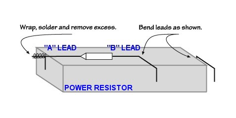
10. Lay thermal fuse RS# 270-1322 across bottom of the new 8 ohm 20 watt resistor RS# 271-0120 with .25" of "A" lead hanging over edge of resistor. Bend resistor lead straight up and wrap around thermal fuse "A" lead. Hold the thermal fuse next to the body with pliers or other heat sink to prevent soldering heat from blowing the fuse and solder the wrapped resistor lead. Trim excess.
11. Line up the resistor assembly to the top edge of the PC board. Using needle nose pliers, make a right angle bend in the "B" lead of the thermal fuse corresponding to the center R1 lead hole in the PCB. Make additional bends in the thermal fuse "B" lead and the 20W resistor's remaining lead to line them up with the R1 lead holes on the PCB. Enlarge the R1 hole that corresponds to the thermal fuse "B" lead.
12. Solder resistor assembly to R1 position on the PC board. Hold the thermal fuse lead with pliers while soldering to keep soldering heat from blowing the fuse.
13. Place and screw down the PC board into position in the chassis.
14. Epoxy the 8 ohm power resistor to the chassis just in front of the PC board as shown below. Place the printed side down against the metal with the leads protruding upward. Note that these leads are live AC and must be routed away from metal and other shorting points.
15. Place the reflector back into position in the chassis and install the lens with the two screws to hold the assembly in place. Bend and place the thermal switch and wires from the power resistor so they will NOT come into contact with the metal reflector or any other shorting points. The thermal fuse will simply sit in the area near R1 and the reflector without touching anything.
16. Carefully inspect your work and the position of the internal parts and wires to insure that they are not pinched or they interfere with other parts.
17. Replace the top cover and the four screws holding
it in place.
Operation:
Simply plug the unit in and turn the knob to the FULL clockwise position. The 60Hz flashes will exactly coincide with the peaks of the AC line sine wave.
Don't leave the unit on for a very long time or it may
overheat and blow the thermal fuse.
Theory:
Since the flash rate is 6 times faster than the unit was originally designed for, the power of the strobe needs to be increased. The unit's input current will go from ~450mA to ~1.2 amps. Thus, the fuse and R1 are replaced with higher power parts. Since the unit may seriously overheat at this higher power level if left on too long, the thermal fuse is added in the area of the light and R1 to shut the unit off if it gets too hot.
C2 is changed from 9uF to 0.5uF to greatly increase the speed at which the circuit will charge. Two standard 1uF capacitors are used with drain resistors.
R4 is removed and the value of R3 is decreased to 220K
ohms to increase the firing rate to ~60Hz. The natural charging pulse to
C1 and C2 at the peak of the AC waveform provides the syncing with the
AC line. The values of C2 and R3 have been chosen to give good locking,
phase sync, and tolerance at 115VAC at 60Hz.
Schematic Diagram Before Modification:
Schematic Diagram After Modification:
AC Line and Pulse Waveform: