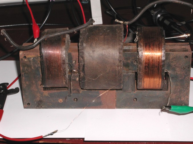
15kV/30mA NST
An Experiment to Examine the Stress on
Neon Sign Transformer Windings
at High Frequency
10-20-2001
Terry Fritz
Introduction: It has been theorized that when a high-frequency signal (Such as from a Tesla coil's primary circuit) is impressed on the output of a neon sign transformer (NST), that the signal's voltage will be concentrated on the outside winding of the transformers high-voltage core. This was believed to contribute to NST failures in Tesla coil applications. The very high inductance of the core along with the stray capacitance, may tend to concentrate a high-voltage high-frequency signal in the small outer portion of the core causing it to fail.
Experiment: In order to test the voltage distribution of a high frequency signal injected into an NST core, the following test was performed.
A 15kV/30mA depotted NST core was set up so that a HP33120a signal generator would inject a signal into the high voltage winding of the NST core. This signal was frequency swept from 10kHz to 510kHz which is a typical range of a Tesla coil primary circuit.

15kV/30mA
NST
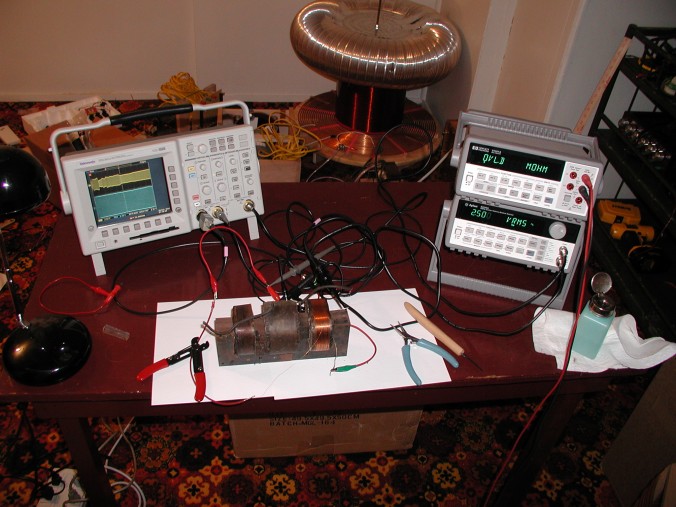
Test
Setup
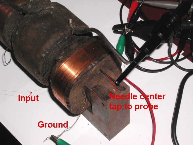
Connections
to NST
Results: A 2.5 VRMS signal sweep from 10kHz to 510kHz was made just tapping the outside winding of the core.
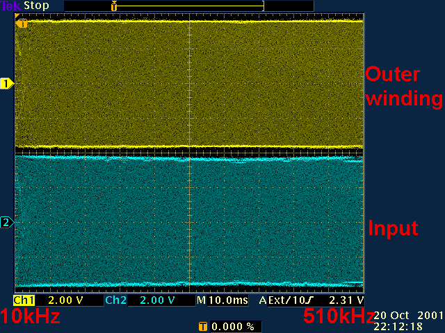
The same signal was measured in the center of the core by inserting a needle into the core.
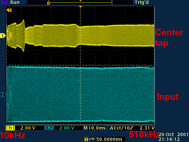
The signal was also tapped about 5 layers (1/8 inch) from the outer winding.
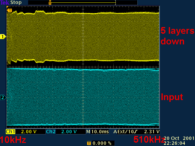
Conclusion: As shown in the above graphs, the voltage on the NST core is very uniform in the frequencies in question. There is no evidence of the voltage being disproportionately concentrated on the outer windings of the high voltage core. This would tend to directly dispute the theory that high frequency signals concentrate in the outer layers of the NST core.
This testing was only done at 2.5 VRMS. It is possible that at 15 kVRMS the core would be energized to a far greater degree and the effects of stray capacitance would be greater.
Many thanks to Billy McKenney for providing the NST used in this testing.