This paper describes measurements of the top and bottom currents in a Tesla coil secondary inductor. These measurements indicate that the secondary is acting as a simple lumped inductor. There appears to be no 1/4 wave effect. The currents are in phase. It appears that the 1/4 wave theory of Tesla coil operation is incorrect. The top terminal appears to be acting as a simple capacitor in parallel with the coils self capacitance. A model for this behavior is presented.
Background: A Tesla coil was equipped with two current probes. The bottom probe was placed inline with the secondary inductors ground wire. The top probe was placed inside the top spherical terminal in such a way as to measure the current flowing into the terminal. The probes were connected to an oscilloscope via fiber-optic cables. The coils parameters are as follows.
Primary firing voltage ~5000 Volts
Primary capacitance 17.05 nF
Primary inductance 118.4 uH
Resonant frequency 112000 Hz
Coupling coefficient 0.1475
Secondary inductance 0.0754 H
Secondary self capacitance 16.68 pF
Top terminal capacitance 10.10 pF
These tests were done with no arc breakout from the top terminal. The spark gap was a multi-gap spark gap with four gaps in use. The coil was quenching at the first notch.
Results:
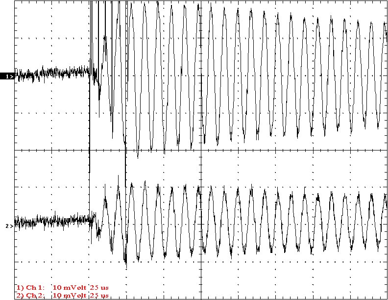
This graph shows the current waveforms
at the base (top trace) and top terminal (bottom trace). The scale is 1
amp per major division and the time scale is 25 uS per division. The primary
quenched after about 30 uS. Note that the current between the top on the
secondary inductor and the terminal is much less than the current at the
base of the secondary.
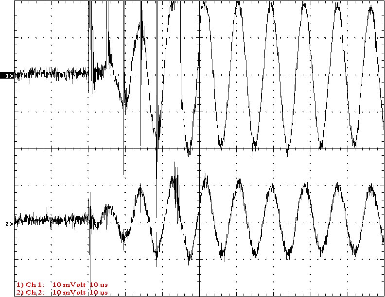
This graph is similar to the last but the time scale is 10 uS per division. Note that the two waveforms are almost perfectly in phase with each other. This is NOT predicted by 1/4 wave theories of secondary operation. But IS predicted by the simple lumped element theories.
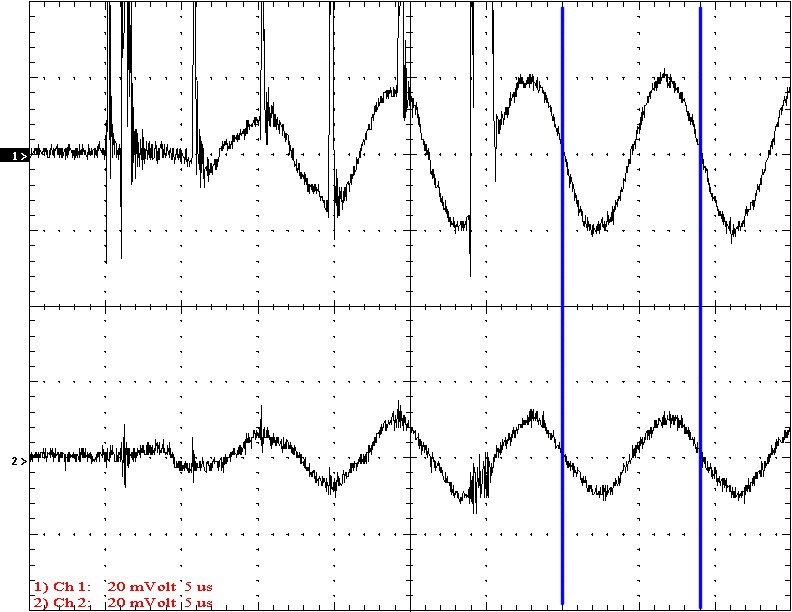
This graph expands the time scale
to 5 uS per division to show the phase relationship between the top and
bottom currents. The scale is 2 amps per division.
The 1/4 wave theory of Tesla coil operation predicts that the current at the base of the coil reaches a maximum while at the same instant the current at the top of the coil reaches a minimum. This would be caused by standing waves if the secondary inductor were acting as an antenna model or transmission line model would predict. These graphs do not support this theory.
The lumped parameter model predicts that the secondary will act as a single simple inductor without standing waves or transmission line effects. The current at the base and top of the secondary would be in phase and equal. The graphs certainly show that the currents are in phase. The difference in the amplitudes of the currents appears to be explainable by considering the self capacitance and the top terminal capacitance as two separate capacitances. The self capacitance appears to be outside the current sensing path while the top terminal capacitance is certainly in the current sense path.
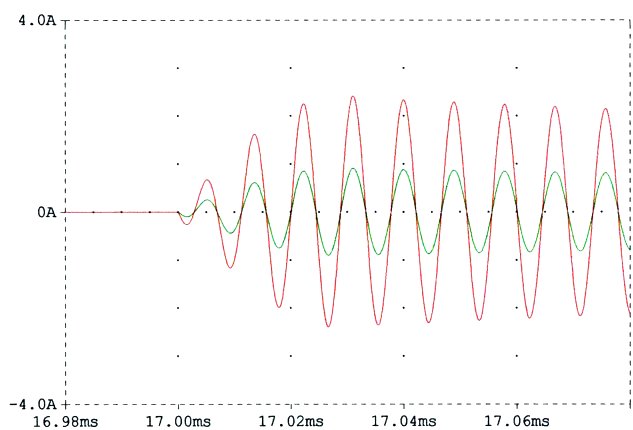
This is a spice model output of a computer model that predicts the behavior seen.
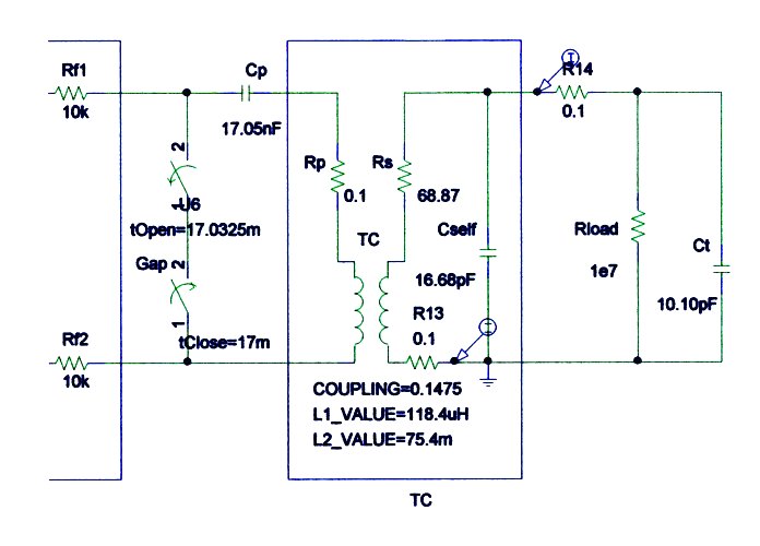
This is the model used for the computer simulation. Note that the bottom current tap is placed directly at the base of the coil while the top current tap is placed between the top of the secondary and the top terminal. The self capacitance of the secondary is left outside of the current sensing path.
Conclusion: The top and bottom currents in the secondary inductor are almost perfectly in phase. If the 1/4 wave model of Tesla coil secondary inductors were true, these currents should be 90 degrees out of phase. However, the lumped element models match the results seen. A spice model (that uses lumped elements) predicts the behavior seen very well. It appears that the 1/4 wave theory of Tesla coil operation is incorrect. The model also accounts for the lower current seen between the top of the secondary and the top terminal. Apparently, the self capacitance of the secondary inductor is acting in parallel with the capacitance of the top terminal and the currents are dividing between the two, as simple calculation would predict.