The usual way to find the linear transformer model parameters of a NST is to measure the open circuit current and voltage to calculate the primary inductance. The secondary inductance is then incorrectly (the transformer is far from ideal, ie. k is not unity) assumed to be the output/input voltage ratio squared times the primary inductance. Several adjustments are then needed to the coupling coefficient and secondary inductance values to get the behaviour of the transformer (short-circuit current, open-circuit voltage etc) right. This iterative process (using PSpice) by trial-and-error is really hard because all parameters are never right at the same time.
With my method you get a very accurate model of your transformer. You only need a handful of values that can all be measured using a ordinary multimeter.
Note that the methods described here should NOT be used with non-limited transformers like distribution or potential transformers. They exhibit a coupling coefficient near unity, so under no circumstances should you attempt to try to measure their short-circuit current. However, a inductively and/or resistively ballasted ďnormalĒ transformer could perhaps be modeled this way.
Please note that the formulas were derived by me from scratch, which was a lot of work. If you decide to include the results of my work on your website, please give me due credit and link to http://www.tr-labs.com/
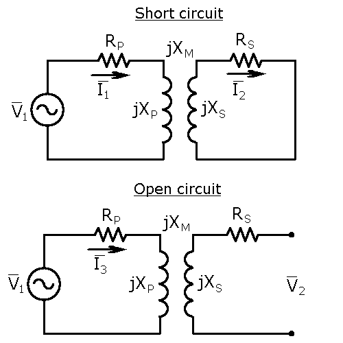
We use two special cases of the linear transformer model to find the model parameters for a current-limited transformer.

Using basic tools of circuit analysis, we write four mesh-current equations that completely describe the above circuits. Please note that voltages and currents are complex quantities.
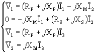
With a little bit of algebraic manipulation:
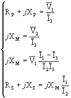
After converting voltages and currents to polar form and taking absolute values of both sides: (voltages and currents are no longer complex)
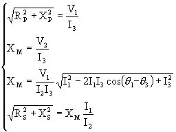
We have four equations but only three unknowns to solve for, so we have to drop one of the equations. Obviously it should be either one of the two equations for XM. Our choice will be the one with the cosine of the phase difference between two currents because we donít know the phase angles. Solving for reactances:
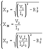
Things can be simplified quite a bit by noting that the wire resistances are in reality very small compared to the inductive reactances. The secondary resistance of a typical NST is about 5kohm while the inductive reactance is about 1Mohm. Because of the square root of difference of squares, the resistances are indeed negligible. If we let RP=RS=0, the error in a typical NST is about 0.001%. Thus we can very well drop the wire resistances.

To calculate the linear transformer model parameters from the above reactances we use the following identities:

Teroís formula for determining the linear transformer model parameters of a current limited transformer:
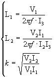
where:
V1 = input voltage [V]
V2 =
secondary open-circuit voltage [V]
I1 = primary short-circuit
current [A]
I2 = secondary short-circuit current [A]
I3
= primary open-circuit current [A]
f = line frequency [Hz]
You need only one instrument, a good multimeter (preferably True-RMS). None
of the values printed on the transformer should be used because they are usually
for average neon tube load.
First measure the line voltage V1.
Note that itís important to use the transformer rated voltage in these
measurements, not much lower or at least not higher, because of the
nonlinearities involved. Don't use a variac because it might interfere with the
measurements (lots of inductance).
To measure V2 you can use a
HV probe or construct a simple 100:1 resistive divider using ten 1Mohm 0.5W and
one 100k 0.5W resistors. Connect all the resistors in series and make sure that
there is enough clearance between all wires so that no arc-over can happen.
Connect the divider ends between the HV terminals of the NST. Carefully measure
the voltage accross the 100k resistor. Multiply this by 100.1 to get the
secondary voltage.
Then you need to measure several currents. First
connect the multimeter in series with the primary winding and apply the input
voltage. Leave the secondary side open. BE CAREFUL as there is several kilovolts
of potential between the HV terminals. Check the meter reading and write it
down. This will be I3. This should be a couple of hundred
mAís.
Then do the same measurement but with the secondary side shorted.
This will be I1. It should be a couple of amps.
Then connect
the multimeter accross the HV terminals to measure secondary short-circuit
current. BE CAREFUL. Ensure that the meter is set to measure current and that
the lead is plugged into the current jack. Otherwise you'll fry your multimeter.
Connect the primary directly to the mains. Note that you donít need to connect
anything to the secondary center-tap. Secondary short circuit current will be
about 25% higher than the NST rated secondary current. Write it down as
I2.
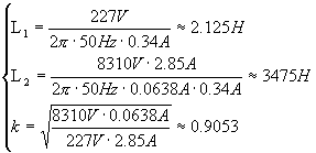
I have a very nice unused 8kV 50mA Neoncomp NST. I used a Wavetek True-RMS multimeter.
V1 = 227V
V2 =
8310V
I1 = 2.85A
I2 = 0.0638A
I3 =
0.34A
f = 50Hz
