A little info
about DRSSTCs
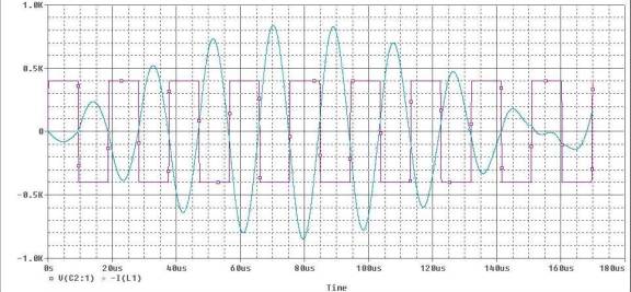
DRSSTC stands for Double Resonant Solid State Tesla Coil. It pulses the secondary with vary high power to simulate a spark gap coil. It uses a half bridge or H-bridge like a normal SSTC, but uses a capacitor in series with the primary. The primary LC is tuned like a normal spark gap coil, and the drive frequency is set to the uncoupled resonant frequency. Using feedback to operate in this mode is tricky, but other modes are possible with secondary feedback. See Steve Ward's ISSTC. It is tuned so that the primary current envelope has notches. It is tuned that way for good power factor. It isn't good to pump a whole bunch of energy into the secondary to have it just come back without transferring much to the secondary.
The first picture is the drive voltage and current
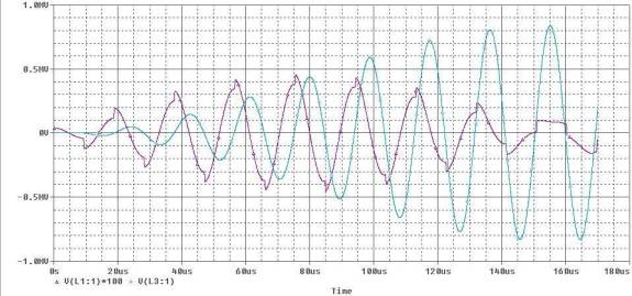
The second picture is the primary and secondary voltages, scaled by the square root of inductance ratio.
The steps are caused by the sharp rise and fall of the driving voltage
There are several advantages over a spark gap coil. DRSSTCs are lighter, as they need no high voltage transformer. They are also more efficient, because there is no lossy spark gap. They're more fun to build of course! More of a challenge also. Since energy is continually being transferred to the secondary, the MMC only has to store 1/4th of the bang energy.
DRSSTCs differ from "normal" (or 60hz) SSTCs in a few ways. The most important way is that the DRSSTC is pulsed, it only runs 10 cycles at a time, and similar break rates to spark gap coils. "normal" SSTCs will run for the whole half cycle, and typically operate on every other half cycle. The second difference is that IGBTs must be used. Some 60hz SSTCs use IGBTs, but most use MOSFETs. The voltage drop across a MOSFET is proportional to the current flowing (it has a fixed resistance). At 1000 amps, this is a problem! IGBTs have a relatively fixed voltage drop of around 2v (they also have a few milliohms though). To allow this much current to flow, more than the rated 20v is needed. By extrapolating the datasheet curves, it is possible to get a good idea of the needed gate voltage. I use 37v, while most SSTCs use 12v. DRSSTCs also have a tuned primary, instead of just a single resonance (hence the DR).
Steve Wards
ISSTC (aka DRSSTC ripoff ;-)) also has two resonances. The primary LC is tuned
to the secondary LC same as any other coil, but the drive frequency is controlled
by secondary feedback. There are no notches in this case. To get a reasonable
power factor, a higher tank impedance and more cycles are needed. This way, the
load pulls the current down somewhat, and there isn't too much energy stored at
the end of the burst.
The advantage of
this setup is the lower RMS current. Some of the loss in the IGBTs is due to
resistance, so this is a plus. The lower current also helps with primary
heating. Although the current is smaller, the higher impedance means lower tank
C, and more capacitors in series instead of parallel. This means hot caps L More caps are
needed to handle the current, even though they aren't limited by energy
storage.