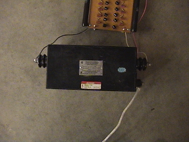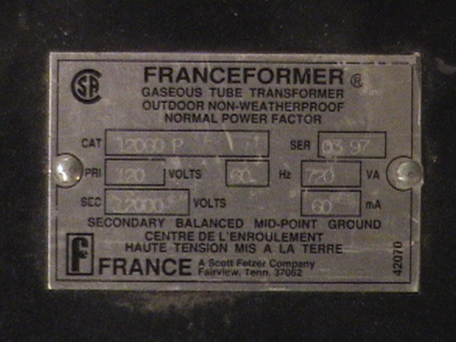
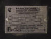
Power Source
- 12 kV, 60mA NST
-
Safety
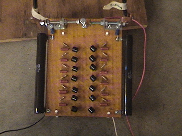
- I used a Terry Fritz Filter. The schematic for
this can be found here. Or at
Terry's Site.
-
-
Capacitor
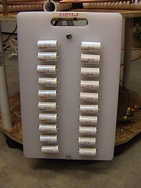
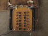
- New Cap: I have made a larger than resonant
cap. It is made of 2 strings of ten 0.1μF
Caps in Series, each with bleeder resistors. The total capacitance of
this cap measures .02038μF.
-
-
-
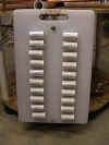
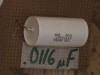
- Old Cap: Geek Group MMC. Nine 0.1μF
Caps in Series (each with bleeder resistor) Total capacitance originally
measured .0116μF, however recent measurements were closer to .0165μF.
-
-
Sparkgap
- New Gap: I now have a SRSG. I am using
an 1800RPM Synchronous motor, and have a saftey gap that is set to fire at
about 80% full power.
-
- Old Gap: I have my gap set at around .25". I have a squirrel cage
blower directed to the gap for quenching.
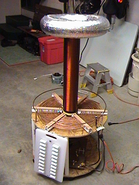
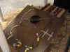
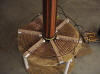
Primary
- Mounted on 1" PVC. I used .25" copper tubing
with .25" spacing. Inner radius is 6" (1.5" from secondary). Total
of 13.5 turns. I hold the tubing in place by placing a layer of
insulating foam on top of the copper, then I screwed some small paneling
strips on top to hold everything snug.
-
-
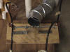
Secondary
- Secondary is 4.5" outer diameter PVC. Wound
with AWG 24 wire to a height of 25.5"
-
-
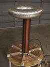
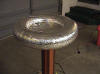
Toroid
- I mounted 4" dryer ducting on an 11" wooden disk.
Then covered everything with aluminum tape. Ended up with an outer
diameter of 19".
-
-
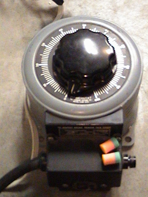
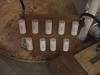
Variac
- I use a 1.1kVA Variac to control the the power going
to my coil. Yes those are ear plugs in the picture.....the coil is
loud indoors.
-

-