
Here I added in some taller heatsinks since the mosfets got warm over 50VDC input. I rechecked the board and the control board to make sure everything was still in working order. I made a few small correction's on the control board to make sure it was running perfectly. Then came some more testing....
Everything ran really well for the first few moment. I got good bushy sparks with my 0.25F smoothing caps. I ran at 50VDC input then moved onto 80VDC. Looked more and more exciting as I cranked up the juice. Then at 103VDC the fuse went. I replaced the fuse which was 6.3A though it blew again even at 20VDC input. I latter found that my 4 Main mosfets had gone totally short. They didn't even get warm with the new heatsinks even at a a few moments running at 80VDC input. Input current on my AMM showed 9amps though this could be incorrect due to the 6.3A fuse. It could be 9amps peek current showing up on my AMM.
9amps is on the high side so I plan to add in a few more turns on my primary to limit the current down a bit. I will try to get the current as low as possible without effecting spark length. I did take a image of the sparks though it turned out too dark to see anything and the SSTC looked a whole lot better in motion than it did in the picture. I will take some more scans when I get running again.
So why did the SSTC driver blow ? Well I doubt it was down to the mostfets being overdriven since they were not even warm. I think there are only 2 possible causes. Firstly the RF radiation from the coil is enough even at low powers to make the auto tune antenna spark off the end. I dare not imagine what all the tracks on the SSTC driver board are having to cope with! The solution here is to keep the SSTC driver well away from the coil and possibly to screen the whole thing in a faraday cage to stop RFI from entering the system. I also feel some overvoltage protection is required on the primary just in case a flashover happens.
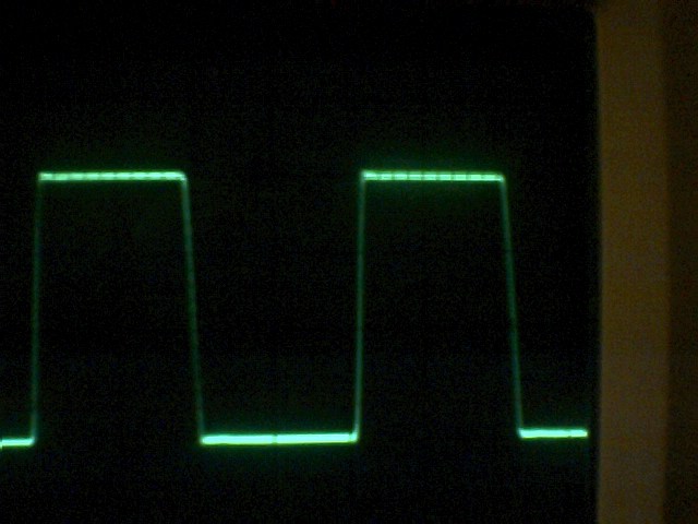
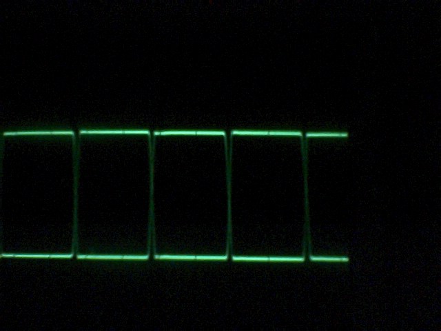
Secondly I discovered that I had a 4volt peek in my drive waveform. I am not happy about the fets being driven with this wave so I took to some investigation. The waves below show the output of the coilcraft coils.
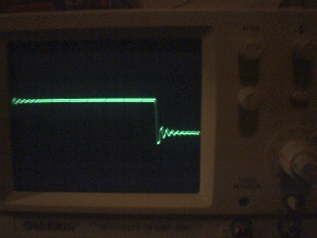
You can see there is a bad peek on the rise of the wave and I want to overcome this problem since I'm not happy about driving the mosfets with this wave.
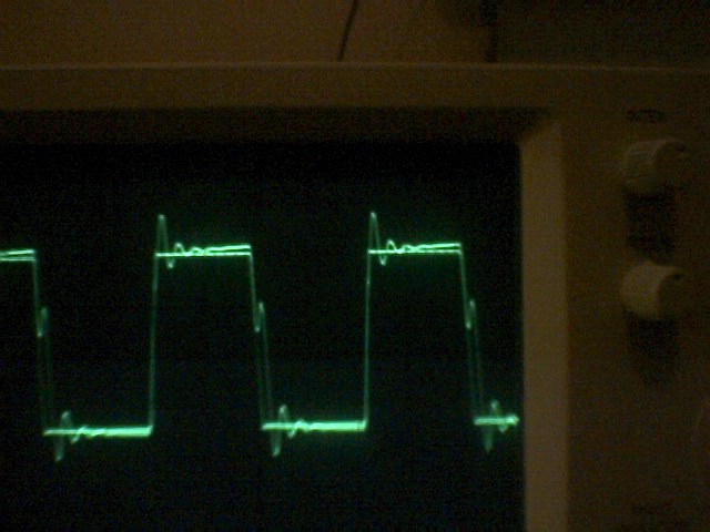
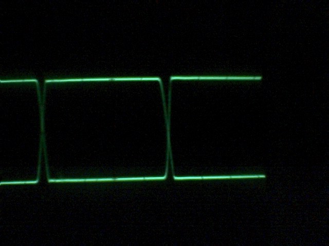
I took some tests just by placing a simple resistor across the output of the coil. The image below is with a 330R resistor...
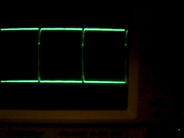
The image on the left is with a 300R resistor across the coil. The image on the right is the original wave.
You can see the resistor has had great effect in smoothing out the "bounce" in the wave. There is no voltage drop on the output of the coil with 300R.
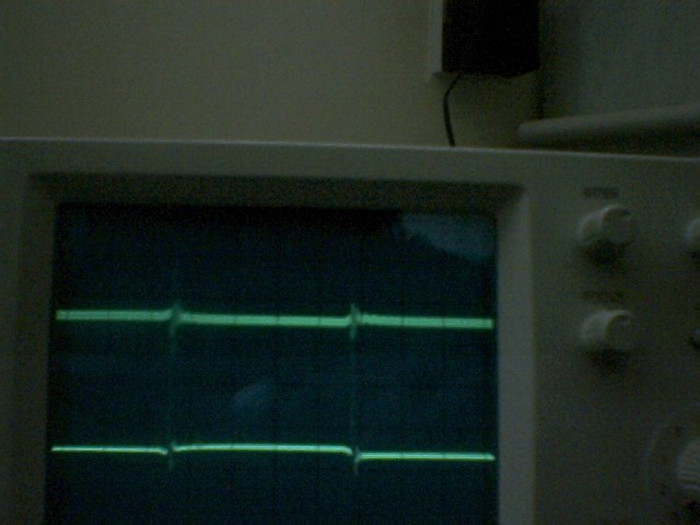
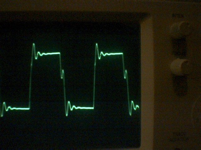
These 2 waves are looking much better with a 100R resistor across the coils. There is however around 1Volt drop on the wave output. I am pleased with that wave and I don't think much can be done to correct it further.
I have some voltage suppressors which I wish to try out over the next few days. The wave voltage looks around to be 10V. I want to clamp down on this wave at anything over 10Volts so I have ordered some suppressors around 10VDC. They should take care of the high peek in the wave though I don't currently know how well they will work. Since a resistor works well I would imagine the VDR's will work the same though not effect the voltage as much.
It seems when the Fets blow the 10R resistors which are in series with the coils start to burn. I will change these for some 1watt types and lower the value to 12R.
The interrupter for the Auto tune doesn't actually do its job and it looks like a slight track route problem. I plan to alter this while im waiting for my new mosfets to arrive.
Once I have the design finalized I hope to buy a bigger PCB tank so I can etch the whole SSTC onto a single PCB. I hope also to add spare for mains sockets, connectors, fuses and a 12V transformer. I don't know when this will be but I hope construction will start fairly soon.
I also hope to fix the current SSTC problems by the end of this week...
After some testing I decided to place a 100R resistor across the output of the coilcraft coils to solve the spike problem. The 10R primary drive resistors have been changed to 12R and 2watt types. The interrupter was a easy fix and I took a 100hz pulse from the raw DC input to gain a nice pulse.
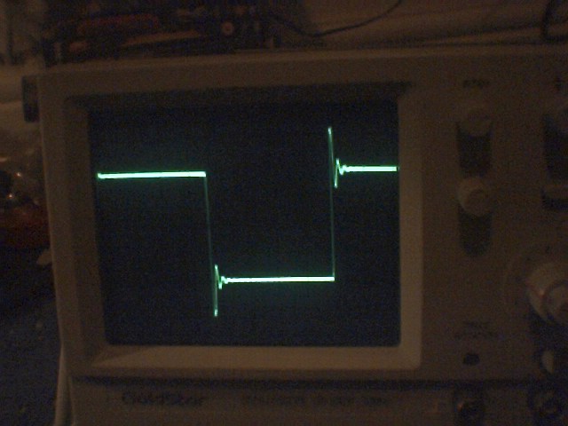
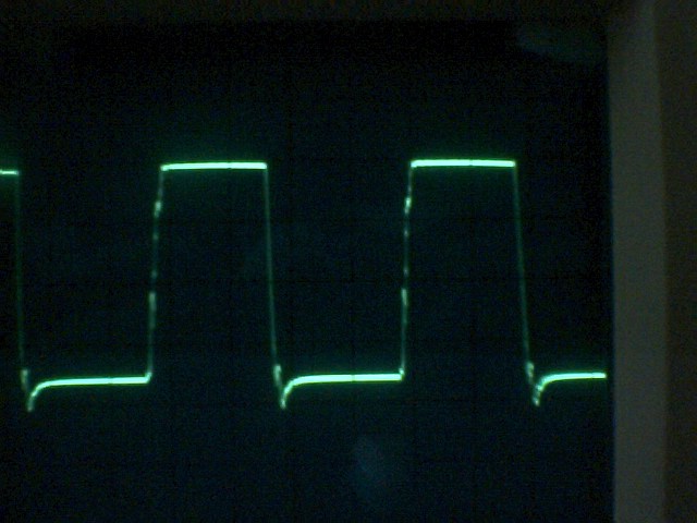
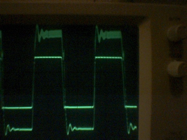
Below is the new gate drive waveform.
Here is the actual H-bridge output wave. There is not much difference between the wave on or off load.
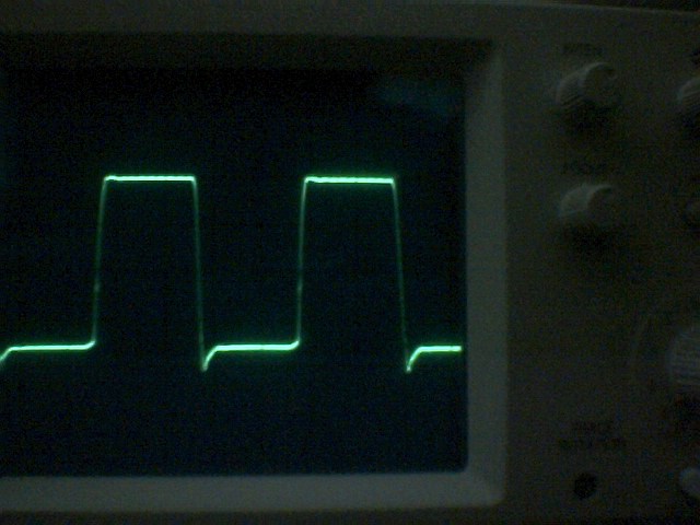
While experimenting I invented my own waveform which I call "The exxos wave". I'm not really sure how it happened though it looked pretty cool so I added it just for fun :)

I hope to test the coil in full action over the next few days. Lets see if I can beat the 103VDC input level :o)
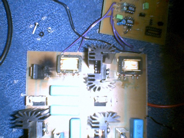
OK so another day another burnt FET..... Here while the coil was running one of the mosfets decided to blow out. Strange thing was the coil was still running despite the board being on fire. This time the board maxed out at 120VDC... Getting better though still a long way off..
The 2 fets on the right of the image test fine. The 2 on the left test short... well the burnt one actually tests a bit leaky but the other one is short.... I noticed the mosfets got rather warm rather quick unlike last run when they ran very much cool. I also rewound my primary from 12 turns to 17 turns and the current draw went from 9 amps to 6 amps. The output spark wise seemed to be about the same. Still only 6" spark output!
My thoughts on this are that since 2 fets have blown in a row I would put it down to a supply short. In this case there still exists a problem with the drive waveform. It would seem for some reason that the deadtime on the TL494 is not doing its job for some reason and the fets are shorting the supply out hence them getting hot very quick... The only cause of the problem here is the isolation coils. I may try removing the coilcraft coils and winding my own coils. I am also thinking that a direct drive system would work a whole lot better. This is drawbacks in doing this though in worst case it can only blow the driver IC's and/or the TL494 which aren't really much of a problem to replace.
I think it should be safe to place a diode in series with a 10K resistor to drive the mosfet gates. In worst case of ground or supply short they current can't flow back though the diode to effect the driver IC's. In a short condition to ground the 10K resistor will stop the IC's from shorting out. I will probably try this idea out when I fix the board.
A test run of the new "Direct drive" was tested out. The direct drive consists of the TC4421 driver IC's feeding the mosfet gates direct via a 12R resistor and a diode. The idea is that should the mosfets short to ground the 12R resistor will limit the current and not blow the driver IC's. Should the mosfets short to the supply the diodes should help prevent the voltage tracking back to the driver IC's.
The mosfet gate wave was a perfect wave as shown below.
The odd problem comes around when the fets are under a small load such as 100R with a 12V input. The output wave has lots of overshoot which looks to be bad. This also then reflects back onto the mosfet gates and distorts the driver waveform.
TEST RESULTS.
Testing turned out to be pretty useless. Current draw was a constant 1amp and Voltage was pushed upto 60VDC. There was enough power to make a tube light up though there was no sparks at all. After a few seconds the 2 top mosfets on the board got very hot and the bottom half fets remained cool. There is no apparent reason why only 2 of the fets are getting warm since these were the 2 which are connected direct to the positive supply rail ( 60VDC ) so I would have thought the bottom 2 fets would also get warm.
It seems For some reason this design will not work. As to why it doesn't the reason is unknown at this time. I will probably go back to the isolation transformers and try them again.

The output of the H-bridge looks pretty much OK though there is still a large spike which can't be seen in the image. This is also present in the coilcraft coils though not as bad as in this case.
It would seem more turns on the self-wound coils would probably benefit in this case. Though I see no reason to at this time to try it out. The coilcraft coils seem the best solution so far. The only other solution to get a better drive to the mosfets would probably be too add a snubber network on each mosfet gate. I will build 1 gate drive and see how it effects the drive wave.

Here I added in the coilcraft coils and used the snubber network. You can see from the image above the wave is so much better than it has been before. I plan to build up all 4 snubber networks over the next couple of days and add in some better diodes!
Above was a quick mockup of the snubber with some 5822 diodes I found in my junk draw. The wave is pretty much perfect! I hope I can get some really good results with the new control design.
For a few more tests I took a scan over the old waveform and the newone ( above ) so you can see the difference the snubber makes to the wave!
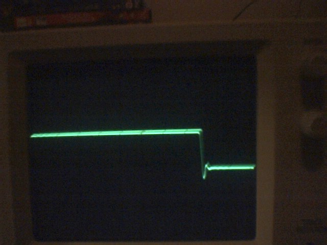
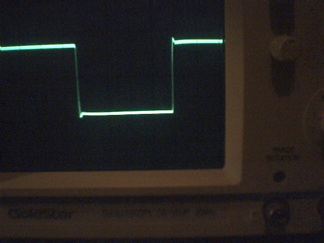
Here is the original waveform with no snubber.You can see the wave is really bad and this is the raw output of the coilcraft coils.
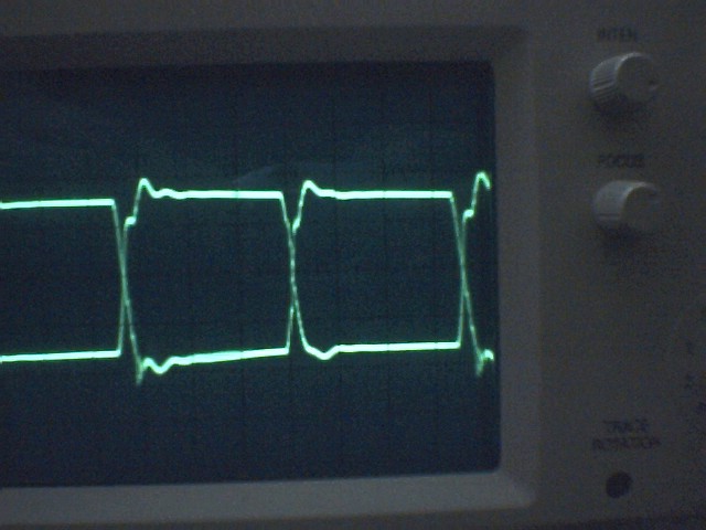
Now I took a test with some power though the H-bridge and this is what happened.
The wave with the snubber is unaffected but the raw wave coming from the coilcraft coils goes out of control. It would seem this is as good of reason as any why my SSTC keeps failing :)
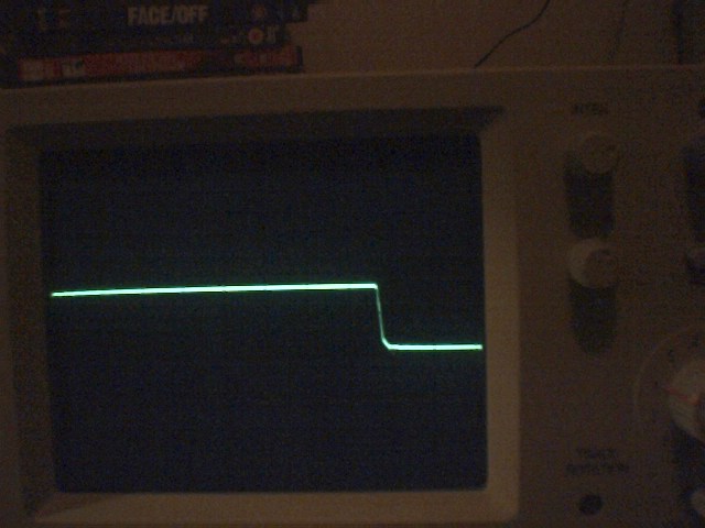
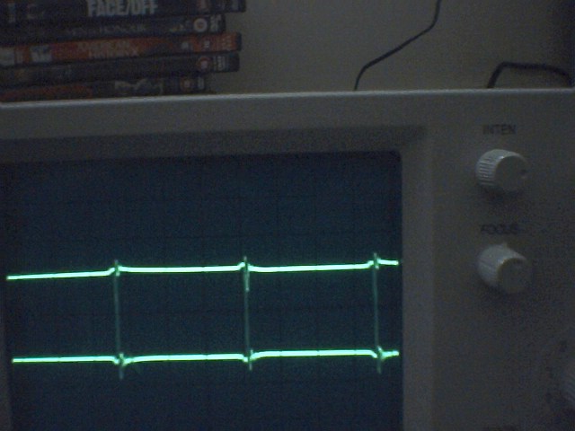
Listed below are the new output waveforms.
You can see the wave looks like its just come out of the TL494! Its hard to think that its going via such a "rough" path and still endsup looking good.
I am pleased on how the mock modifications turned out. It will be a little work to add this onto the main H-bridge board though I plan to build a little adapter board which the coilcraft coils plug into. This small add-on board will have the full snubber circuit on each winding.
Will I pass the 120VDC 6" spark barrier....... tune in soon to find out! :)