
Conclusion.
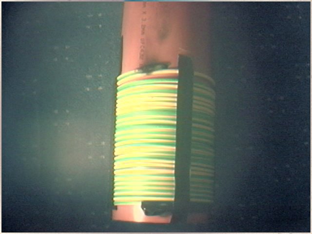
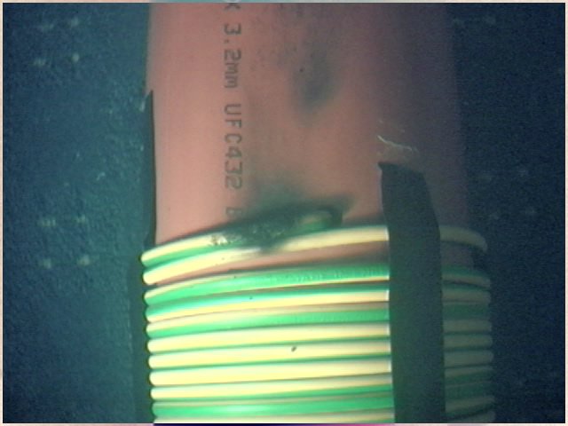
It would seem apparent that a small diameter primary is required to increase the gap between the 2 coils. It is also a must to also lower the winding height of the primary itself. I plan to wind a new primary on 2.5" tube and use slightly thinner stranded cable. It just goes to show how strong these arcs can be! All this mess and still not gone over 40VDC input into the driver board!
One thing which I am thinking about now is to build a driver coil and base feed the secondary coil. Its clear that insulation is going to be a real big problem. Should the new primary yet again fail, which no doubt it will, I may try some thinner cable and only have a winding height of maybe 1 or 2" from the secondary base. It is very clear that half way up the coil there is enough voltage to arc though 1" or more of insulation. Base feeding the secondary is looking like a more attractive solution.
One good thing, if you can call it that, Is the SSTC itself has not yet failed! Even though its been running on around 40VDC input so far its withstood a fair old bashing so far. The only thing which I had problems with was the grounding for 0VDC for the mains input to the driver. For some yet unknown reason the ground wire between the control board and driver board melted. This was seems also the cause for my variac to hum loud when going over 20VDC. I don't see any problems in not having the 2 board grounds connected. They both should be at 0V though I imagine the variac itself could be the cause of this since the 0V on the DC side isn't connected to ground. I will investigate further into this.
February 20, 2003
Today I made a quick smaller primary to see how well it would work. This test primary was wound with 2.5mm multistraned wire. A total of 30 turns wound on a 2.5"dia tube. Testing proved that it was very much limiting over the original primary. I guess of around 50% power loss with this new primary coil. It is clear that the original primary is the best solution though it will prove a challenge to insulate it.
February 21, 2003
I tried various other coils to see how they would perform. My best working coil is my 0.2mm 17"high coil ~2000 turns. I tried a 0.4mm 34"high and gave no spark output. Current draw was only about 1amp from the 30VDC input test voltage. With the 0.2mm coil I could draw 6amps with 30VDC input. I thought it may be because the coupling was less since the coil was taller. I put this to the test and wound a test primary direct ontop of the coil. This proved to be of no benefit. I went mad and wound about 15" of coax cable directly ontop of the 0.4mm coil to give the same area of coupling which the smaller coil had. This proved to work even less than the other 2 primary tests.
I also tried a 18"high coil wound with 0.4mm wire ~1000 turns and this gave poor results the same as the previous coil. I also tried a 40"high coil wound with 0.8mm wire and about 500turns and gave even less results. I can only assume now that poor coupling is not the reason why the coils do not work well and it is down to the use of 0.2mm wire with 2000 turns. I would have thought 0.4mm wire with 2000 turns would work the same if not better though it doesn't work even with more coupling.
This now proves a interesting puzzle since with my spark gap coil tests the bigger the wire was the better the results I got were. Now with my SSTC I can only see that the thinner wire works better. I don't see why 0.2mm 2000turns works better than 0.4mm 2000 turns. With 0.2mm wire I recall the resistance was very high around 2K. I recall my 0.4mm coil was around 200R so should give far better results. I now wonder on winding a test coil with 0.2mm with 1000turns to see what would happen. I also ponder about winding a 0.1mm wire coil 2000turns...
March 2, 2003
Work over the last few days was taken out in coupling tests. I basically found that providing the primary was around 1/2" by the secondary then this would give the best power transfer. I didn't find any benefits to the thickness of wire or the number of turns. The best primary so far does appear to be the yellow coil as shown at the top of this page. These tests were also reflected upon the SSTC CURRENT page.
March 20, 2003
Many coil tests were done and it was found that around 12 turns worked best for the primary. There does seem to be a strange inductance relationship between the secondary and primary. Higher inductance secondary make the SSTC draw more current from the board. Less primary turns also make the SSTC draw more current. After many tests with coils I agree with Richie's basic guide below..
The current draw depends on the following things:
1. The base impedance looking into the Tesla Resonator, (or if you prefer the Q factor of the resonator.) Low base impedance, (or high Q) resonator draws more current than a coil with higher base impedance (and lower Q) from an identical driver.
2. The coupling coefficient. High k values mean that the primary sees more of the secondary turns so the step up ratio is higher.This means the secondary is effectively fed from a higher voltage so draws more current than if the k was lower.
3. The number of secondary turns. More is better because it increases the Q. Ls goes up with turns squared, but R only increases proportional to number of turns. Therefore Q goes up.
4. The number of primary turns. Less turns gives a higher step-up ratio feeding the secondary and presents a lower impedance to the driver. Therefore low numbers of primary turns will draw more current than primaries with lots of turns.
March 23, 2003
With all the secondary coils I tried the smaller 0.2mm wound coil gave good results. My 0.4mm wound coil also gave very good results. Though with the 0.4mm wound coil current draw was half since it was much less inductance than the 0.2mm coil.In order to attempt to boost the current draw on the 0.4mm wound coil I used fewer turns on the primary. Current draw went much higher though spark output was never any better. Both coils had around 2000 turns.
I latter tried a 0.8mm wound coil which only had around 500 turns. Inductance was very low and didn't draw much current. I used fewer primary turns again to try and boost the input again, with no success. I latter tried increasing the input voltage which did seem to help with the thicker wire coils, though when the wattage in was calculated it still wasn't as good as the 0.2mm coil.
After much testing it would seem a high inductance secondary works best with a lower input voltage of around 40VDC. When inductance halves input voltage needs to be double to get the same results. This does seem to hold true since every coil I tried with lower inductance needed more input voltage. I also tried a 1.6mm wound coil 500turns and this gave almost no output no matter what the input voltage was or number of primary turns.
The interesting thing comes when I tried a "out of the blue" ( as I call it ) coil. This coil is shown below.

This coil was wound with 2.5mm multistrand plastic insulated wire. I guess this to be around 500 turns. The black winding on the coil is a length of 100meters of wire. The coil almost uses 4 drums at 100meters. Wire rating was 600V at around 10amps. I found that 500 turns of 1.6mm wire gave no output at all, though 500turns of normal multistrand wire gave a whole lot better results. In actual fact for the same power input the plastic wire worked better than my 0.2mm wire secondary ( which up to now has been the best ). I didn't think this was correct so I didn't many coil swaps from all my coils and took tests again. I concluded that this multistrand coil worked better than any other of my coils. The reason for this is not yet known.
I have a coil wound with 1.6mm magnet wire, about 500 turns. This gives
no spark output at all inductance is about 30mH so it draws about 1 amp
at
50VDC input ,So we will call this 50watts.So now I tried my plastic wire
coil ,about 80" high 6.3"dia , basically same number of turns
and length of wire,
though the plastic wire coil is only 5mH. Now this coil draws 0.5amp at
180VDC this gave 1" spark output. Now my 0.2mm wound coil also gives
1" spark at the same input wattage. Basically both coils have the
same input power and same output power and both give the same results.
I think this is interesting since with the plastic wire coil the voltage should be I think a lot less but it works just as well. Now my thoughts are the 0.2mm coil has high resistance wire which will give losses, the plastic wire coil has almost nothing for resistance because of the skin effect on many many strands of wire so Q is a lot more, BUT, because the wire is insulated voltage must be less, so Q is many not as good.... I think its very interesting about these results. It now makes me think to wind a coil with plastic insulated wire, many small strands, and with as little insulation thickness as possible. I think this would prove a interesting coil to try! You may remember my 0.4mm coil works better than 0.2 even though same length of wire. I think surface area is more with 0.4mm so its better Q, coils wound with plastic wire, I think, if done correctly, can be even better.
What I want to try is a coil wound with litz wire. It would be interesting to wind a coil with the same length of wire as my plastic insulated wire coil and have the same O/D as the wire. Trying to keep all the specs of the coil as close as possible but use litz wire. The litz wire would have around 20 totally insulated strands whereas my plastic insulated wire wound coil would have maybe 50strands but of course not insulated from eachother. Resistance at the higher frequency's would be a lot less, This is a must since the coil would be low inductance the coil would run at a much higher frequency so losses should be a lot more. litz wire would help to overcome this and should give interesting results.
These conductors in litz wire have more surface area since every single
strand is isolated from the others by furnishing it. In this way, the
current can use all the many little surfaces of all the brands separate,
which give much more surface area than when using the one (big) surface
of the entire cable. The skin effect is totally negligible at frequencies
lower then 50Khz.
It makes a interesting dilemma that lower inductance coils such as my 0.2mm wound coil run at around 100khz. You can them imagine that the skin effect on this coil is nothing much to worry about. The DC resistance of the wire is something to also take into account. If you then compare to my plastic wire wound coil which runs at near 600khz the skin effect plays a big part in this coil. The many strands of wire make a larger surface area which gains back some of the losses, such as the fact that the turns are spaced out due to the plastic insulation of the wire. Another interesting point which I haven't pointed out is my plasticwire coil is only 500 turns, whereas my 0.2mm coil is more at 2000turns. If you compare 500turns of 1.6mm solid magnet wire this gave poor results. At a very rough guess is 2000 turns gave me 1" spark , then 500 turns is 1/4 of this so sparks would be 1/4".
Since my plastic wire coil gave 1" spark with 500 turns then something has improved the Q of the coil. Since there are much fewer turns then you would expect the coil to give lower output. Since the turns are also spaced, again lowering the Q of the coil. Higher running frequency which should give more losses also lowering Q. In all respects Q is lowered in many areas but it still works just as good as my 0.2mm wound coil. Skin effect is the only explanation since the wire is multistrand. Note that my 1.6mm wound coil gave no sparks at all which should be a higher Q than the plastic wire wound coil.
It also makes me now wonder what would happen with 2000turn plastic insulated wire wound coil. Since this coil can give 1" sparks and had 1500 less turns on it than my 0.2mm coil which also gave 1" sparks for the same input power, then it would seem logical that 2000turns would give even better results. This is not possible since the coil would be over 300" high! a insane project! The only alternative is to prove the skin effect by litz wire. There is however one problem which I imagine I will encounter with litz wire which coil cause problems. This comes about since when you link 2 inductors in parallel inductance halves. I don't know if this would hold true for litz wire but I would imagine it will have some effect. This now generates the problem than 20 coils in parallel ( 20 small insulated strand internal to the litz wire ) would give much lower inductance than 5mH with my plastic wire wound coil. This would then increase the frequency and also give lower inductance and draw less power from the SSTC, which will give worse results.
It would make a interesting test though the cost of litz wire is a fair bit over my hobbie budget at the moment. If anyone knows of a good source (n preferably in the UK ) then please let me know!
More tests to be done soon!