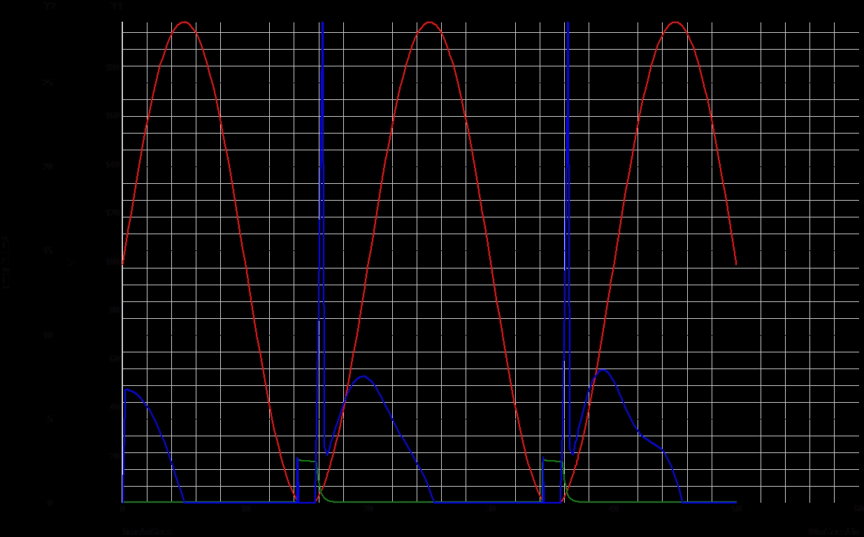
Tank Charge,
RED = Dirty DC (100hz) , BLUE = Tank Charge current, GREEN = IGBT Gate voltage
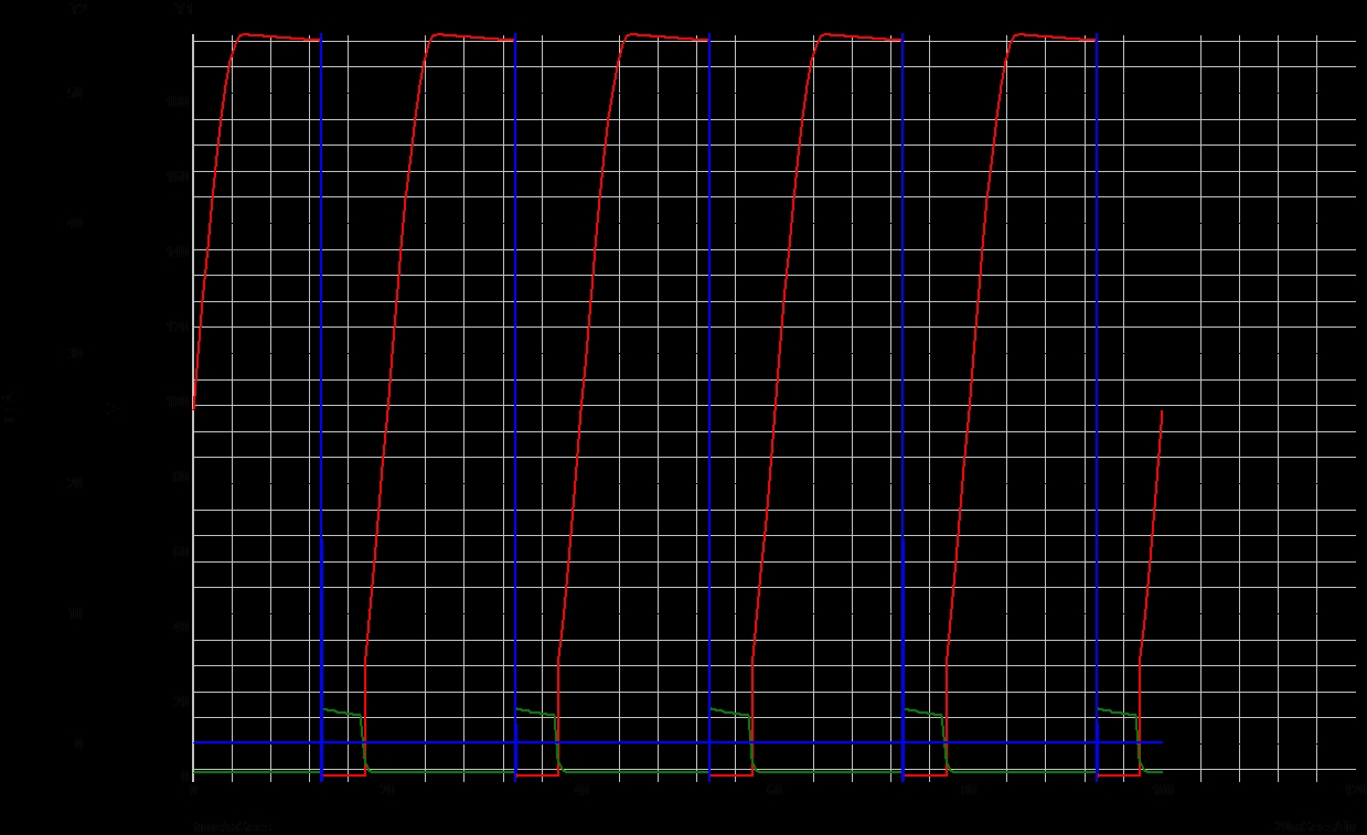
GAP VOLTAGE/CURRENT
RED = GAP VOLTAGE, BLUE = GAP CURRENT, GREEN = IGBT GATE VOLTAGE.
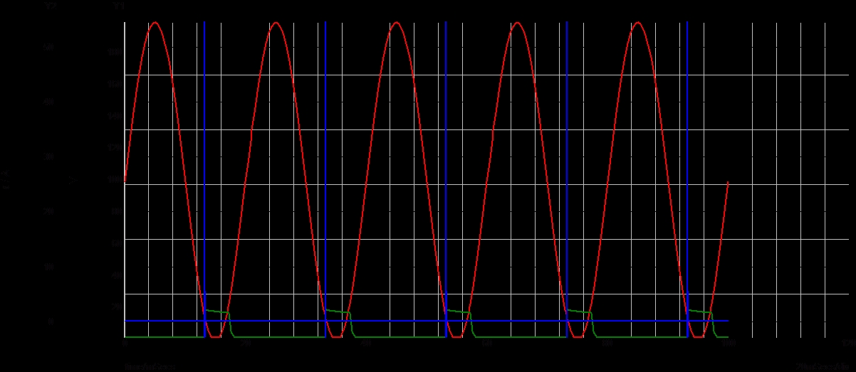
GAP FIRE PULSE
RED = DIRTY DC IN (100hz), BLUE = GAP FIRE CURRENT, GREEN = IGBT GATE VOLTAGE.
GAP FIRES - When input voltage (RED) falls below appox 4volts. This prevents IGBT from shorting out the supply rails as the switch is synced to low part of the cycle.
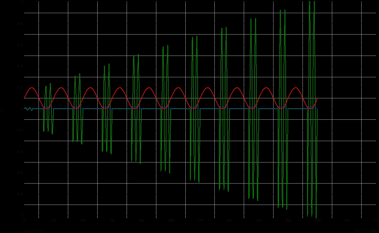
RESONATE RISE
RED= DIRT DC INPUT VOLTAGE (100hz), BLUE = IGBT GATE VOLTAGE, GREEN = HT OUTPUT VOLTAGE.
GREEN WAVE - Low frequency just to prove concept. Probably not 100% accurate but you get the idea ;-)
Below, simulation diagram.
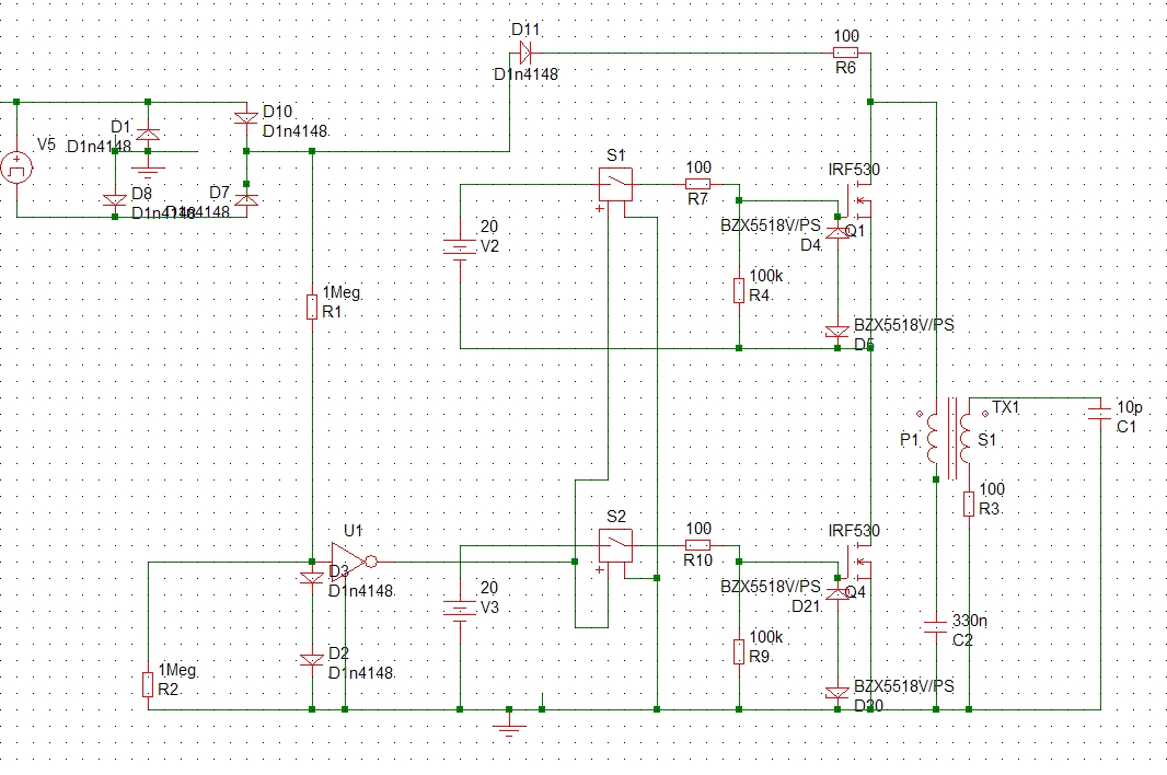
Basic outline. I call it "SSSGTC", "Solid State Spark Gap Telsa Coil" ;-) I had the idea for this circuit a lot long time ago , but didnt see it come to light until Terry built his first OLTC :))
Ignore the part numbers, too lazy to edit them. Here all fets are off while the AC line charges C2. D11 helps prevent C2 from discharging as the cycle falls. Once the cycle gets below about 2 volts (set by D2,D3) with 2 volt threshold of U1. Once the mains cycle drops down below the threshold level the fets Q1,Q4 turn on dumping the charge in C2 across P1. Bascially exactly the same as a spark gap coil but with much better control and lower losses.
"twiddles" over Terrys SISG design...... The BSP rate is locked onto the mains cycle for perefect firing of 100BPS. There is no shorting of the charge resistor (D11) as the fets fire on the low side of the mains cycle not at the peek!. The notch point can be adjusted by altering the threshhold voltage of the circuit U1,D2,D3,R2. Setting the trigger level to 10volts would mean a longer fet ON time. Reducing the threshold will reduce the ON time and the sooner the fets will turn off. Increasing the "ringing time" will also burn up a few more mA's in the charge resistor D11 though at 10volts its only very low.
S1,S2 are actually opto isolators with a floating supply rails V2,V3. The "hickup" is that I had to get the transformers custom made to stand 10,000volts between primary and secondary windings! The good thing is that all mosfets will fire bascially at the same time, and there is good regulation with floating supply rails. R4,R9 discharge the mosfet gates turning them off. A lower value may work better though its hard to say from simulation since the actual parts are not there :-( Zeners (BZX) are 18V and limits the gate voltage to about 19volts.
Only 2 "sections" are listed, there is no limit as such to the amount of sections which can be linked in series, I plan to build 6 such sections. This would give a max voltage of 7200V and peek 1200amps. Problem is as the number of fets go up so does the resistance of the fets, so it may be a trade off between a few things.. At least the tank caps will last a bit longer due to a higher fet junction resistance ;-)
Parts should be here in about a weeks time, hopefully will see some flash in one respect or another very soon :-)))