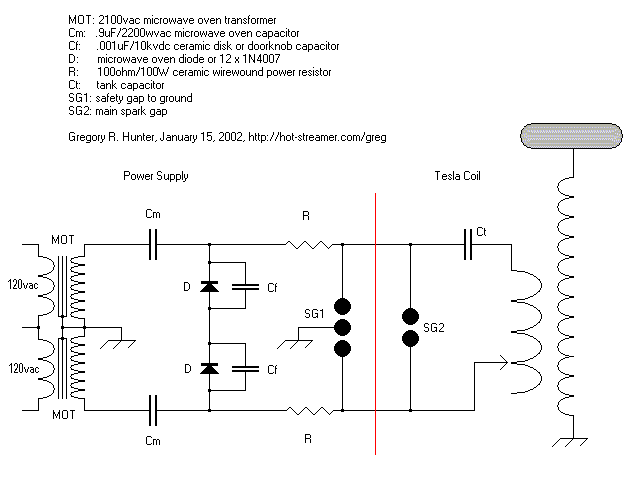
This is a schematic of my dual MOT power supply with voltage doublers. Theory of operation is pretty straightforward. On the first half-cycle, the two diodes (D) are forward biased and the two doubler capacitors (Cm) charge to the peak potential available from the MOT twins. On the second half-cycle, MOT current reverses and the diodes are reversed biased and behave like an open circuit. This places the secondaries of the two MOTs in series with the charged doubler capacitors (Cm). The sum of all four potentials is felt across cut-off diodes, making a
12KVDC pulse of up to several hundred milliamps available to the Tesla tank circuit through the power resistors (R). This is the classic voltage doubler or "level shifter" circuit, which has been around since the genesis of electronics. The wire-wound power resistors (R) along with bypass capacitors (Cf) form an RC low-pass filter intended to attenuate any RF feedback from the Tesla coil. So far I have experienced no RF heating of the silicon diodes or the Mylar MOT caps, so I guess it works. The final output is in the form of 12KVDC pulses at 60Hz. I don't use any filtering or smoothing--I just apply the raw output to the Tesla tank circuit. I can distinctly hear the 60Hz pulsing when the coil runs.