Greg's (Old) Tesla Coil Page
Current performance: 12' @ 9600 watts! - Real photos soon!
Go to bottom of page for spark images
Contact me at s371034@student.uq.edu.au
Information contained in this page is for educational use only. You can easily kill yourself attempting these experiments. I assume no liability for any injuries, etc caused as a result of this page!
This is my old six inch coil (made back in `95 when I was 15) doing its thing. This coil used a 0.03uF primary tank cap and my 11kV pole pig in its final setup. Spark gap was an asynchronous rotary, probably running at about 750BPS in this photo. Spark length is about 6 feet. This is tiny compared to my new 12" coil that is now making easy 12 footers :)
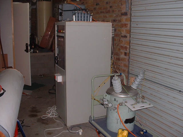
These photos show my PDT and controller cabinet used for powering my new 12" coil. The PDT is rated at 10kVA with 11550V on the primary and 250V on the secondary. The safety gap is attached to the front of the PDT. The power cabinet is an old Hewlett Packard computer reel to reel tape unit for a mainframe. I scored it for free from uni. On top of the cabinet is my SRSG phase controller. Inside the cabinet are contactor relays, variacs, line filters, paralleling chokes etc. There are 3 30amp variacs inside, though I am only using two in parallel at the moment, as a 60 amp continuous rating is plenty for me at the current time. I may wire in the third variac one day though.
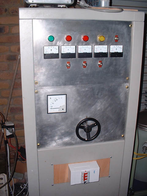
The second photo shows the panel detail of the controller cabinet. The big square meter is an 80A current meter, using a curent transformer. The smaller meters are, from left, line voltage, variac 1 current, variac 2 current, auxillary current (for SRSG), voltage out (to PDT). The lights show when various parts of the cabinet are energised. The small switches control the contactors. The big red switch is a 100A breaker, and I also have HRC fuses inside the cabinet.
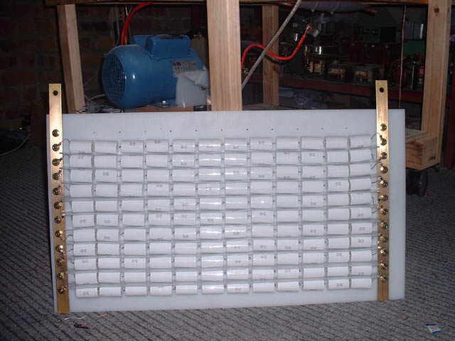
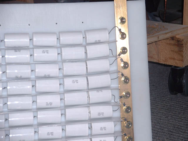
This is my new MMC cap. It uses 12 strings of 12 0.15uF, 2kVDC Cornell Dubilier polypropylene film/foil caps for 0.15uF at 24kVDC . One string is yet to be soldered into place in this photo.
The HV rails are 1" wide brass stock. There is a sheet of 1.5mm LDPE between each string to prevent any flashovers and damage to adjacent caps should one explode. The MMC is constructed on 10mm thick HDPE and the 10M bleeder resistors are on the reverse side.
The coil is currently running a 200BPS synchronous rotary gap.

This is my homemade ballast, wound from 16mm2 stranded wire on a "spare" 10kVA pole pig core I had lying around. The current is controlled by varying the air gap between the two "c" cores with plastic shims.
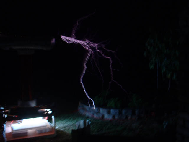
This is my secondary burning up. Note the red hot turn at the
base of the secondary. There are no racing arcs and no visible arcs to the
primary. One arc over at
10kVA and the coil is instantly ruined! Coupling is MUCH more critical at 10kVA
than I ever imagined. Despite the shorted turn, the coil is throwing 10 footers
at this point, and easily does 12 with the new secondary.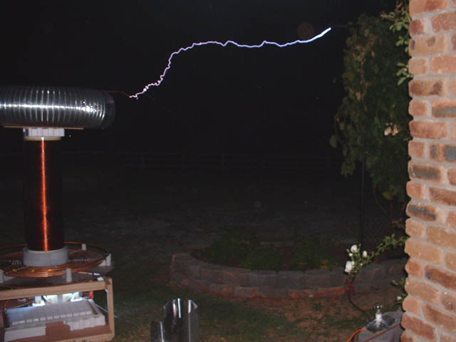
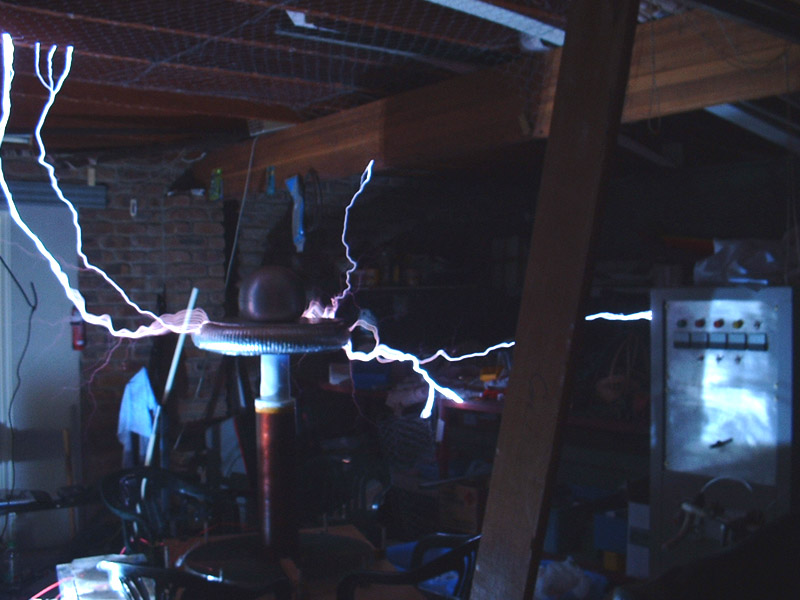
Well, I quickly fixed the above secondary by rewinding the bottom 4" of the coil with some 2.5mm2 stranded PVC insulated wire. Here is a nice arc to a fence, 9 feet distant. Notice how hot the arc is. This coil does this easily. The exposure was taken using a flash (accident), and was very short, as my digital camera has no manual functions. Total power is probably around 7-8kVA, though I'm not exactly sure as I don't trust my current meter much. The system is protected by a 32 amp fast blow ceramic HRC fuse, so I guess the power can't be too much more than that (32A at 240V).
UPDATE - current draw measured at 38-40 amps, with 12 foot arcs. Using new 1300 turn secondary.
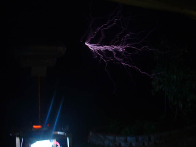
This is a pretty poor picture of a ground strike by the coil. None of the above photos do this coil justice. Much more impressive in person.