Chester's White LED Lights

I recently bought 20 white LED lights from http://www.whitelightled.com/ and have been experimenting with them ever since, very fun :)
Single LED CO2 Cartrige Light
(click to enlarge pictures)
![]()
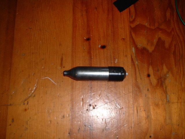
Empty 12 gram CO2 cartrige that i used in a friends paintball gun (i dont have my own gun yet) these should be fairly easy to find, if you know a place where they play paintball im sure the people there would be more than happy to give you some empty cartriges, usually they just get thrown on the field because your trying to change it so fast.
One of the first things i built was a single LED flashlight using an empty 12gram CO2 cylinder as the housing. I discovered by experimenting that 3 of the six alkaline batteries found inside a single 9v alkaline battery fit perfectly inside the cylinder when the back is cut off, this can be done with a hacksaw or similar device, i used a metal cutting bandsaw. I also had drill the hole in the front end larger so the led would fit, i ended up making it to large though so i had to secure the led with hotglue which i dripped down from the back, since the hotglue didnt stick very well i used CA (super ) glue over the hotglue which had formed into the shape of the front of the cartrige with the led stuck in the middle, i then put it back into the cylinder and its been holding ever since..........
The batteries fit so tight in there that i put a pice of sold copper wire over the front so that after i pushed them in i could pull them back out again with that wire. The switch is a push button that came from a broken VCR (it controlled some setting and was hidden by a front panel) its not momentay but instead stays on when you push it which is what i like my switches to do. I have seen switches similar to this in digikey and mouser ...... i prefer to reuse parts, mostly because i dont like waiting for them to be shipped in to hawaii (takes about 5 days). Also the switch i used was alredy connected to a PCB so i just the PCB into a circle with wire cutters with the switch in the middle, i cut it just right so that it fits snugly into the end of the CO2 cartrige after the 3 AAAA or whatever size thoes things from the 9v are were put in, with some electrical tape inbetween so as not to short out anythign :)
Oh and dont forget the all important 45 ohm resistor, the value is not that critical although it does determine the brightness of the light and how long the light will last.............. again, my resistor was salvaged from an old VGA computer monitor it is the small 1/8th watt variety so it doesnt take up much room. Its placement in the circuit doesnt matter, as long as it is in seris somewhere, mine was soldered directly to the switch.
I then taped the back of the co2 cylinder in place with some electrical tape because i couldnt think of a better way to attach it, if you can think of one let me know !! soldering it isnt possible because that would melt all the contents :) like the plastic around each of the batteries that keeps them from shorting out to the case............
The finished product :) what most of you wanted to see
View from the top, i like the simplicity of the design, if only the tape wasnt there it would look pretty damn cool, not that it already doesnt ;)
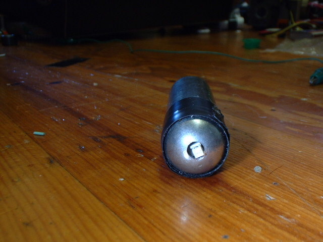
Here is a picture from the back showing the switch, and the messy tape job
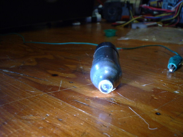
Here is a view from the front showing the single LED, which is suprisingly very bright, for its size and power consumption.
10 LED PWM controlled super light
Same picture as at the top of page, just thought id put it here for reference
This flashlight uses 3 C batteries and should have a nice long run time, it has a 10 led array that i made with Nichia white LEDs.

 this
is a picture of the flashlight with the steel coupler removed, i may put in
some kind of lense if it becomes necessary, right now there is none.
this
is a picture of the flashlight with the steel coupler removed, i may put in
some kind of lense if it becomes necessary, right now there is none.
All the LEDs are connected in parallel and are seris connected to the power supply via a 1 ohm resisitor and the PWM circuit.
The PWM (Pulse Width Modulation) circuit i used can be found on this page about LED lights OddOne's White LED page . Contrary to his schematic i run my 555 timer circuit from 4.5 V DC and it works fine, also because of the low voltage used it is "OK" to use little or no resitor. The best way i think to determine the resitor needed it to measure the actual current draw, each LED is rated for 30 MA so the array should be able to draw 300 MA and still be within operating conditions, i found that with the PWM circuit connected and no resitor the LEDs were only drawing an average of 220 MA so i was going to put no resistor, but then decided to put a 1 ohm 1/2 watt in there just of safetys sake....... also, my flashlight includes a ON-OFF-ON 3 position toggle swtich that changes the PWM frequency by putting either a .1 uf or a .45 uf capacitor in parallel with the normal operating cap of .001 uf. By doing this i lower the operating frequency down to about 10 HZ (rough estimate, i didnt do the math) with the .1 uf and about 1 HZ with the .45 uf. By doing this i also eliminated the regulatory function of the PWM circuit, so if you turn the duty cycle up to about 98 % the leds are brighter with the .1 than with the .001 and they also draw more.
Here are upto date operating conditions of the flahslight:
With 5.6 volt coming from 3 brand new alkaline C batts, about 5 MA is being
used by the PWM circuit
--- Average current ---
PWM on full with .001 uf = 190 MA
PWM on full with .1 uf = 220 MA (the output has a slight flicker of 10hz or so when that 98% or so duty cycle kicks in)
PWM on full with .45 uf = 220 MA (same as with the .1 except the interval between barely noticeable flicker is longer, about 2hz )

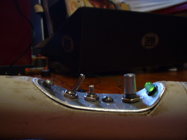
Here is a picture of the controlls for the light from left to right they are:
1) ON-ON toggle switch that turns the whole apartaus on and
off/
2) ON-OFF-ON toggle swithc that changes the flashing rate, middle is to fast
to see
3) 1 M potentiometer that changes the duty cycle
4) green LED that lets you know the light is on, this was needed because when
the duty cycle is at 0% it appears that the light it off
Same as above except from a different angle.
The body of the flashlight is made from 1" PVC and was
threaded just like you would a 1" steel pipe, unless you have your own
pipe threader you may find this hard to accomplish and may need to find another
solution to the problem.......
The recess in the pipe for the controll panel was but with a bandsaw and then
smoothed with a spindle sander and then a pneumatic hand sander with 100 grit
paper. The panel was also roughly cut on the bandsaw and then sanded down
until it fit well.
 Picture
from the back with the endcap removed, one battery was also removed so you
could see everything..
Picture
from the back with the endcap removed, one battery was also removed so you
could see everything..
The power from the negative side of the 3 batteries gets back up to the controll
section via a 24 guage bare copper wire, i would have used an insulated one
but there wasnt enough room on the side of the batteries, besides, they are
insulated anyway. Now that i think about it another solution would have been
to use enameled coper wire like on my telsa coil, well unless i have a problem
this should be fine........
The coper wire you see was actually heated up with the soldering iron and
then stuck into the PVC so its very snug in there, its not the most elegant
design, but it works and was easy to build.
The positive battery contactor is actually a pice of dowel that fit perfectly in the 1" PVC, i drilled a hole through it and soldered a wire to the negative terminal of a C battery which i ripped from the battery, then hot glued it to the flat side of the dowel chunk, the wire is also fed through the hole. This pice of dowel then rests against one of the screws that holds the controll panel in place.
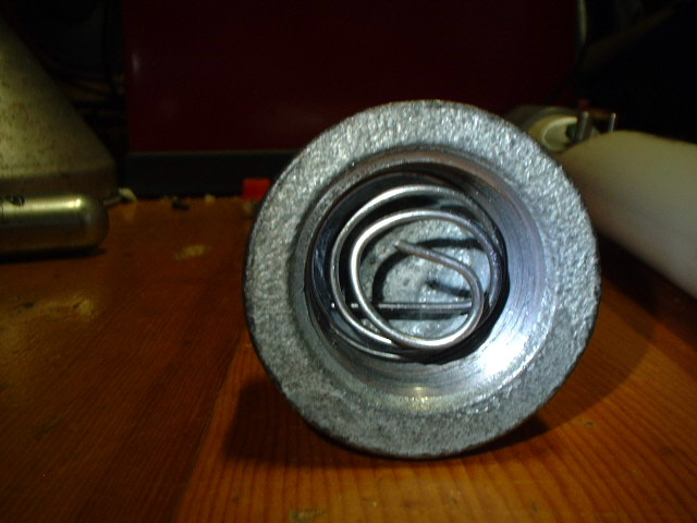
Here is a picture of the steel endcap, I made the spring out of stainless
steel wire, it works quite well.
WELL, i think thats it, there is probably lots i have left out,
if anyone notices anything missiong, or just has a question, id be happy to
answer it :)
Email: hilo90mhz@hotmail.com
BACK
to the index