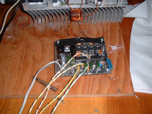
The main pulse generating section of my driver uses two seperate chips, one
to generate the high frequency(180-450 Khz) and one to interrupt this high
frequency at a much lower frequency (1-20khz) depending on what timing resistor
and capacitor I use (the resistor is variable of course). The duty cycle is
also fully variable from 0-100 %.
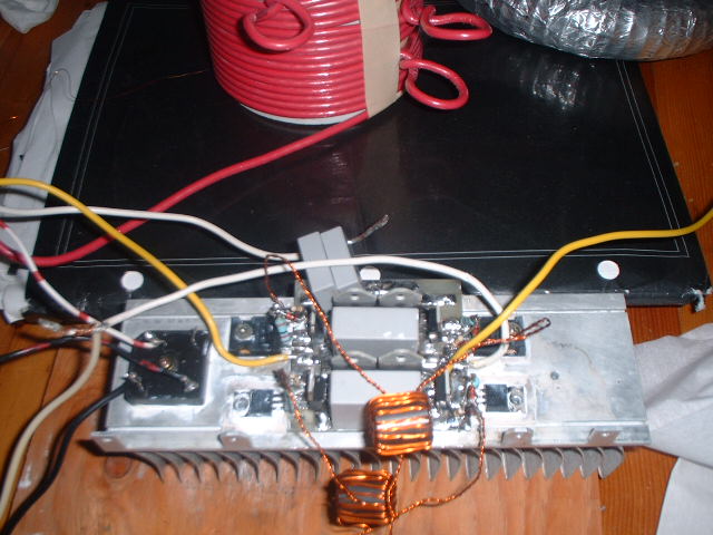
The ourput from the pulse generating section is fed into 2 TC4422CPA (non
inverting) and 2 TC4421CPA (inverting) mosfet driver ICs. These chips amplify
the signal considerably and power the isolation transformers that connect
the driver section of my SSTC with the high power H-Bridge section.
All the windings for the two isolation transformers are 16 turns, and each
transformer has 3 winding, one primary and two secondaries. The secondaries
are connected in anti phase, meaning that while one is high, the other is
low, and the primaries of the two isolation transformers are connected in
anti phase too the mosfet drive ICs. The windings are trifilar, meaning that
before I wound them on the ferrite cores I twisted the 3 wires together, this
helps keep out interference
The Schematic was created with some share ware program that i downloaded,
it works OK, but I still have to find a schematic editing program that I like
as much as the PCB desiging program is use. If you find any errors please
let me know.
Driver Schematic: Color/BW (good for printing)
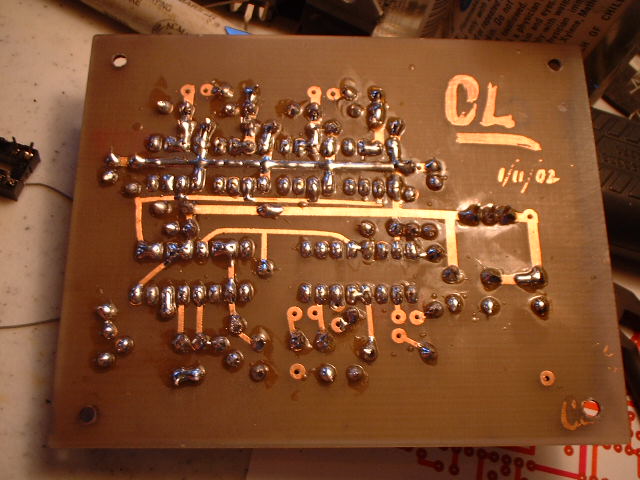
The PCB was created with Board Editor, see the links section of my page for
more info.
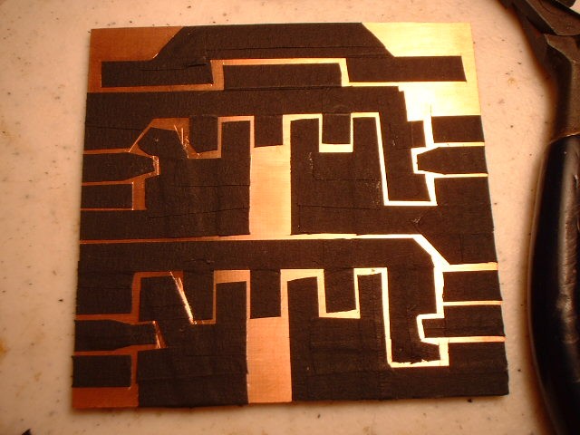
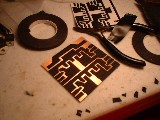
The bottom side was made using the tape method, but for the top side/ground
plane I used a sharpie marker, going around the pins that I didnt want connected
to ground. This method gives good shielding and also makes desiging the bottom
side of the board considerably easier because you just leave all the ground
connections blank and deal with them on the top.
Driver PCB: Bottom/Top/Stuffing
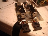
Actual Pictures: Ground Plane/ Half Finished Board/ Bottom half finished
board/ The board as it currently sits
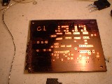
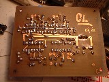
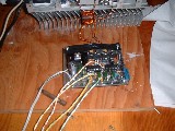
If you look at the picture of the current board you may see that there are
some modifications to it, and that some pins of the ICs were pulled out of
their sockets and soldered to in ordrer to change the design after the fact,
I made the board before I had the final design. But the schematic above includes
all these modifications.
H-Bridge:
The schematic for my H-Bridge is almost identical to Richie
Burnet's whos page can be found in the links section of my site. It is a standard
mosfet H-Bridge, with bypassing of the mosfets internal intrisic diodes. However
the parts I used for my coil were all different from the ones on Richie's
schematic, mainly because of availability. But the ones I used are equivalent,
if not higher rated.
Parts Based on prices from Mouser Electronics
| C1-2 |
.47 uF 275VAC |
Polypropylene Suppression Capacitor |
$1.02 |
$2.04 |
| C3-4 |
1 uF 275VAC |
Polypropylene Suppression Capacitor |
$2.50 |
$5.00 |
| D1 |
Diode |
35A 400V Diode |
$2.00 |
$2.00 |
| D2-5 |
MUR3060PT |
30A 600V Ultra Fast Rectifier, Dual |
$3.50 |
$14.00 |
| D6-13 |
1N4744A |
15V 1W Zener Diodes |
$0.14 |
$1.12 |
| D14-17 |
MBR2545CT |
25A 45V Schottky Rectifier, Dual |
$1.58 |
$6.32 |
| Q1-4 |
IRFP460 |
18A 500V N Channel Mosfet |
$3.20 |
$12.8 |
| R1-2,6,8 |
12Ohm 1W |
Metal Film Resistors, Not That Critical |
$0.10 |
$0.40 |
| R3-5,7 |
1KOhm 1/4W |
Carbon Film Resistors |
$0.04 |
$0.12 |
| T1-2 |
16/16/16 Turn |
EMI Ferrite Suppression core, Free |
Free |
Free |
| |
|
|
|
$43.8 |
This parts list does not take into account all the parts you
will blow in the process of perfecting your design :) I spent $ 140 originally
on all the parts for my coil, which included double of all the parst in the
above list, and triple of the mosfets. The main reason for that is that I
live in Hawaii and if a part breaks I cant go to the local electroncs shop
(we dont have one) and pick it up, I have to order it and that takes preciouse
time. I also want to build a better looking coil after i learn alot on my
current one, and that one i can show people and stuff, whereas the other one
i will experiment with. But im not going to start on it till i get my current
one running reliably.
The second time I also ordered enough parts to make a simple
coil designed to run off 120V AC using 4 IRF740, based on my experience with
my current coil it should produce 10 inch sparks easily and only cost about
25 $ in parts. I want to try and make this coil very small and professional
looking, hopefully without to many modifications, doubtfull :).
Sofar the only parts I have blown are 10 Mosfets, 2 Schottky Rectifiers, and
some 15V Zeners which I didn't count.
Schematic: Color/BW
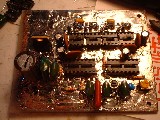
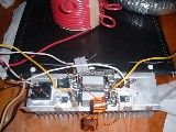
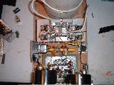
For my PCB design I chose to mount all the components on the
top of the board, so that I could mount it ontop of the heatsink, and keep
all leads as short as possible. Even though none of the components I used
were surface mount ;). I think the design came out pretty good, and its not
very hard to change blown mosfets (they will blow !!).
H-Bridge PCB: Top/Stuffing
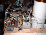
This board was made in escentially the same way as the driver
board, excepy I made the traces as large as possible, and the board was only
single sided. So far it has withstood 10 dead mosfets :) and if you look at
the last picture you will notice that the two mosfets on the bottom half of
the bridge aren't IRFP460, but instead IRF740. Thats because I had only bought
12 mosfets and didnt want to wait for the other ones that i had ordered.
Suprisingly the IRF740 ($1.60) performed very well, and for half the price
of the IRFP460 ($ 3.20) they almost persuaded me to give up on the IRFP460,
and if I had to redesign the whole bridge I would probably use 2 IRF740 in
parallel for each leg of the H-Bridge.
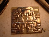
Actual Pictures: Tape on copper/same/Etched copper
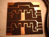
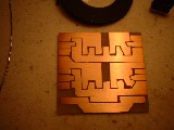
Solder tinned copper/ some components in place /Present condition
Actual Coils:
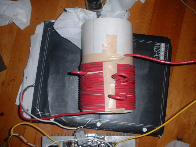
My primary and secondy are basically copies of Richie Burnett's coil.
Primary: 6" long 4" diameter PVC (actual 4.2"
OD) 10AWG Stranded copper wire, tapped at 7/12/16/20 turn.
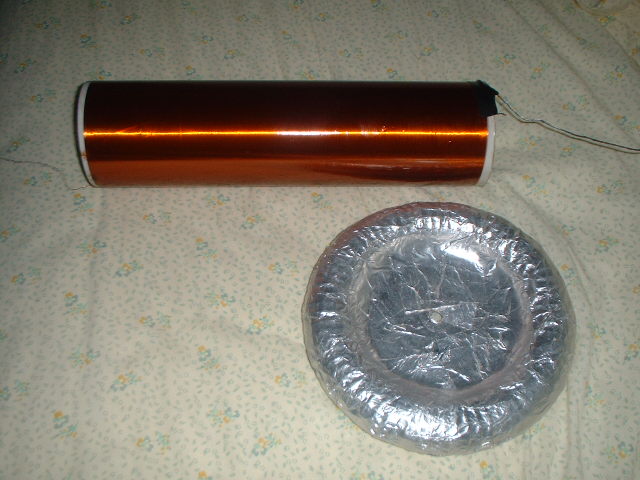
Secondary: 13" long 3" diameter PVC (actual 3.5"
OD) 30AWG Enameled copper wire, 1200 turns.
The secondary was wound on a wood lathe which was turn by hand,
the wire was fed directly from the spool, with me moving the spool along a
steel bar to keep the wire from overlaping, or leaving space inbetween each
turn. It was then painted with polyester surfboard resin while still on the
lathe so I could get it coated evenly. After the resin dries it is almost
indestructable and is fairly well insulated also. I learned from previous
experience, that if you leave the secondary uncoated, the wire will get cut.
Pictures: Primary/Secondary and Toroid

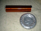
Thoes things sticking up from the primary are tap points, I
havent yet cut the insulation away from them though.
The toroid was made from some old vacuum cleaner tubing, with some thick wide
tape wraped around the tubing to help smooth out the ridges. Then a cardboard
disk was inserted in the middle and the whole thing was covered with strips
of aluminum foil sprayed with 3M adhesive spray. It is 1.5" high and
7" wide.
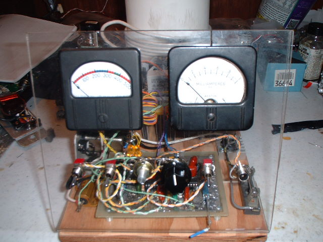
SSTC-Version 2.0
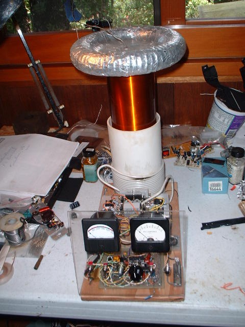
Here is my second SSTC, The design is almost the same as the
first but incorporates a few changes in circuit design, this time both the
PCBs were made using the photo etch method, I also incorporated a signal out
jack so that can connect my other SSTC together with this one but in antiphase
and get double the spark length between them :)
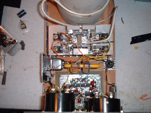
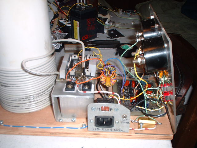
Front controll panel / Top view / Left side view / Right side
view
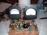

The two analog meters are for current and voltage, so i have
some idea of what the coil is drawing. The side pannel has connections for
input power (via standard 3prong computer powersupply connector), small 1/8"
jack for 12v DC power and a switch of the type used in computer powersupplys
to switch between 120/240v input, instead im using it to switch between full/half
wave rectified DC using a full wave rectifier you can see on the right side.
Im also using a 7amp fuse for protection and a .05 ohm resistor/shunt to measure
current.
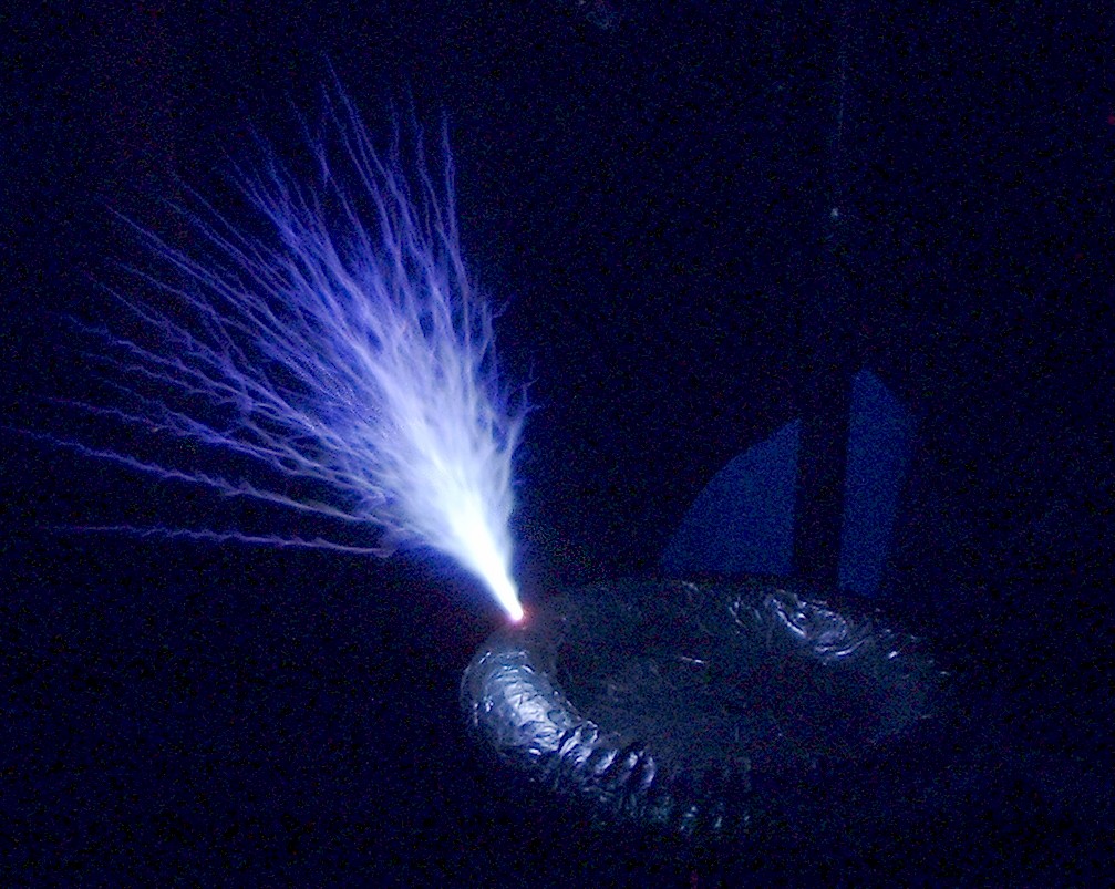
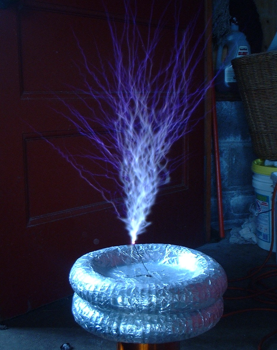
Spark Pictures:
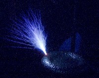
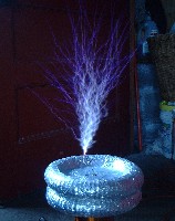
120v input 1/2 wave rectified / 240v input l/2 wave rectified
(~250Kb each) The sparks look alot better in person, my digital camera cant
capture them very well. I modified the left picture to try to get them to
stand out better, it kindove worked, they also look more grainy.
Email: hilo90mhz@hotmail.com
- I also use MSN messenger if you would like to talk, just add me.
HOME