This page describes my Tesla coil (TC) project for those who are interested. There's a ton of stuff
available that explains how these things work in detail so I'll just give the basic idea here.
The TC operates on the principle of resonance, or more specifically, two resonating electrical circuits (LC tanks) that
are magnetically coupled together. The first circuit (primary) stores energy from a power source and then
creates a strong oscillating magnetic pulse when a switch is closed. This field is applied
at the base of the second circuit (secondary), which hopefully by intent of the builder, is tuned to the exact same
frequency as the primary circuit. As a result of the mutual magnetic coupling, energy is transferred from the
primary circuit to the secondary circuit. Due to the high impedance of the second circuit,
huge voltages are generated at the top load (big doughnut thingy). The voltages can reach tens of thousands
to millions of Volts, depending on the coil particulars and power level. Large arcs or streamers are emitted from
the top load since the electric field intensity there exceeds the ionization threshold of air.
The reason I decided to build a Tesla coil is for one, I like watching big ol sparks, and two, as anyone who's searched
for "Tesla Coil" on Google would testify, they are really fascinating devices. Additionally I like the idea
that you have to build your own since they don't sell them at Fry's Electronics. As an added benefit, owning a TC is
sort of status symbol amongst geeks, similar as what a nice car is to normal people. The more you think about it,
why the heck would you NOT want to build one.
Okay, I would be somewhat remiss if I didn't make any mention about how incredibly dangerous these things are
and that anyone who doesn't know what they're doing hasn't got any business messing around with them. Its
true. A good overview of the safety issues concerning working with Tesla Coils and high voltages can be found
here.
The following describes my present coil. Currently I'm in the process of rebuilding it with a new secondary and another
primary cap to increase the overall power level. I will update this page as developments are made. I also am working
on a 220kV Marx generator that can be triggered a 10 pps.
Thanks for looking!
Dave Lewis
My Coil Specs
Power source:
Power control via a 15A 0-140VAC Variac.
2 - 15kV 60mA Neon sign transformers (NST) in parallel.
NST protection filter (RLC) with transient absorbers (aka Terry Fritz):
Circuit values per side
R = 5kOhm 50W (these get too hot - I need bigger ones!)
C = 330pF (10ea in series, 3300pF 1600V Polypropylene with 10M Ohm 1/2W bleeder)
L = 2mH (750T #34 on 3/4" PVC sch40 pipe, wind 6", R=51Ohm)
Z = 15ea. in series, 625Vac/1000V Transient Absorbers, DigiKey part# PD7261
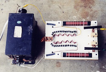
One of my NSTs (left) with the protection filter board (right). The filter has two legs as can be seen.
Each leg features a resistor, inductor, capacitor, and transient surge absorber. The purpose is twofold, (1)
to prevent harmful voltages from entering the NST and thereby protecting it and (2) to also help reduce the amount of
the electrical noise created by the coil from entering my house power lines and messing up something really
important.
Primary Circuit Capacitor:
0.03uF 35kV Maxwell Pulse Capacitor (will be adding a 2nd one on my upgrade)
Primary Circuit Coil:
Main coil...
- 11 turns of 1/4" copper tubing
- ID 7", OD 23", 3/4" spacing per turn
- 15deg incline
- coil tapped at 8 turns
- coil positioned 1/2" above bottom turn of secondary coil
The coil is mounted on an adjustable platform that can be raised and lowered for tuning.
Tuning coil (in series with primary coil)...
- 18 turns of 3/8 inch copper tubing.
- 4.5" diameter, 3/8" spacing per turn.
- tapped at 10 turns
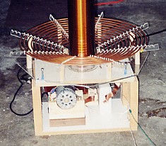
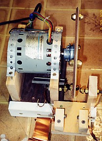
The primary coil - ie. the big spiral thing-a-ma-bob. The tuning coil isn't shown since I had made it yet
when the picture was taken. But the primary capacitor can be seen (white block at the lower left)
as well as the back of the rotary gap motor.
I believe in tuning coils to obtain the best possible tune. I don't subscribe to the fractional turn stuff
that some people go by. All fractional turns do is move the connection leads around in different paths thereby
making a bit more or less inductance that way. Its not necessarily true that 10.2 turns is always less inductance
than 10.5 turns. If the lead length to stretch out to where 10.2 is tapped is much longer that the 10.5 tap point
then the overall inductance might even be greater.
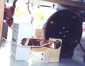
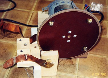
Close up of the primary cap and rotary gap. The tuning coil isn't in these pictures either. I used some
nice 1 inch wide copper foil to hook it all up. The foil by virtue of its large surface area has a very
low resistance at high frequencies as a result of the "skin effect". Low resistance is a good thing.
Rotary Spark Gap:
120 breaks per second.
7" fiber glass disk with 4 brass electrodes at 90 degree intervals on a 6" diameter.
Motronics Hysteresis Motor, 1800RPM, 110Vac, 1.3uF Cap.
Built in safety gap consisting of two pan head screws 5/8" apart.
The spark gap is really the heart of the whole thing. Its the switch that
fires off the primary circuit which in turn causes the secondary circuit to resonate like hell. My spark
gap is a rotary type. The motor spins a disk with electrodes that connect the circuit 120 times a second.
One interesting thing that happened was that on my first few runs the fiber glass disk was getting severely
burnt next to each electrode. The cause was due to spark's path curving in towards the fiber glass since
it fires before the electrodes line straight up (advance). I fixed the problem by cutting 1" wide slots
into the disk next to each electrode thereby preventing the arc from striking any fiber glass at all.
This worked very nice (no more burns), makes a very satisfying whooshing noise when its spinning, and
gave the disk a cool look.
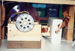
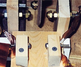
Here's a better view of the gap itself. The upper two brass nuts are
the stationary electrodes. The rotating disk presents the moving electrodes between the stationary
ones with a very small clearance. This functions as an ON-OFF switch as the electrodes line up
and then separate. The arcing in the gap with the coil running is like that of an arc welder. Its
extremely bright and hot. The gap is where most of the wasted power ends up (ie. power that is not
manifested as an arc, but just waste heat).
Rotary Gap Phase Adjuster:
Used to adjust the gap timing +/- 30 degrees while coil is running
- L = Powerstat 10C 2.25A Variac
- C = 15uF 220Vac with 5A fuse.
Handy On/Off switch
This was needed because I used that crappy hysteresis motor for the rotary gap. When the motor spins up, I
have no way to control the gap timing. So first I "rough it in" with a few flicks of the ON-OFF switch and
then use the phase adjuster to fine tune for maximum spark length.
Secondary Coil:
5" diameter, 27.5" long...
- 950 turns of 22 AWG (thats 1250ft of wire)
- wound on an Acrylic (plexiglass) form.
- L = 20mH, R = 20 Ohms, Self capacitance = 10.5pF
Heavily coated with a polyurethane varnish for enhanced voltage stand off
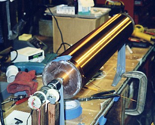
Here is the secondary coil being wound. To put the 950 turns on it, I
jury-rigged a lathe style winding setup from a couple of "L" brackets and an old cordless drill motor.
I used an adjustable power supply to drive the motor and control the winding speed. Once it was all set up
it only took about 20 minutes to wind the whole thing. With the loose ends of the wire taped in place I
then applied several coats of varnish. To get the varnish on nice and even and allow some thick coats without
any dripping, I left motor running while it dried.
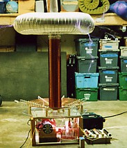
Top Load:
7" Aluminum dryer ducting from Home Depot bent into a toroid shape.
Diameter = 31"
Capacitance = 33.8pF
Toroid positioned 2" above top turn on secondary coil
Bending this ducting into a doughnut shape was not easy. I pretty much suck at it.
There are numerous dents plus a big ol hole as a result of my wrestling with it. When the coil runs, the arcs
all concentrate where my shoddy workmanship is. I get multiple arcs simultaneously instead of a nice big
single one. Having multiple arcs is not optimum since a single arc would be bigger, and thats the name of
the game here... big arcs. Making a smoother toroid will be my next improvement.
RF Ground:
10 foot 3/4 copper pipe sunk in the ground.
12 ft of #2 copper wire runs from the pipe to the TC secondary return.
Primary Ground:
Xfmr cases are grounded to the 100Vac 60Hz ground.
NST protection filter return is strapped to the xfmr cases
.... yeah.. yeah.. I know this isn't best way but I did it any ways... so there.
Operating Characteristics:
Resonant frequency = 160kHz
Power draw = aprox 1000W (rough estimate)
Spark length = 4 feet
Noise level is really loud :-) (I'm glad I got COOL neighbors)
All right, Enough of that Technical Crap
......Lets See It GO!
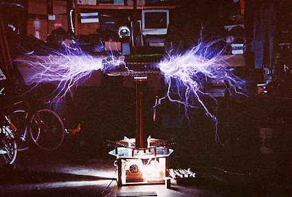
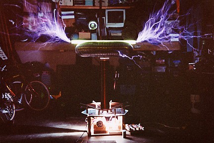
Here it is running in all its glory at full power (Oct 2002).
The long time exposure used for this picture creates an illusion that the sucker is on fire,
but its really not.
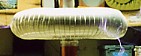
In this picture a 3 foot fluorescent light tube is sitting
on top of the toroid. The whole tube is lit with nice arcs coming out each end. This ended up
being kind of hard on the light tube as you might imagine. Later inspection revealed small holes
were punched through the glass where it made contact with the toroid.
I'd like to thank Terry Fritz of hot-streamer for the awesome hosting
of this web page. A BIG thanks to all the knowledgable folks on the
Telsa Coil Mailing List
for the wealth of invaluable information that they so generously and graciously provide.
 The TC operates on the principle of resonance, or more specifically, two resonating electrical circuits (LC tanks) that
are magnetically coupled together. The first circuit (primary) stores energy from a power source and then
creates a strong oscillating magnetic pulse when a switch is closed. This field is applied
at the base of the second circuit (secondary), which hopefully by intent of the builder, is tuned to the exact same
frequency as the primary circuit. As a result of the mutual magnetic coupling, energy is transferred from the
primary circuit to the secondary circuit. Due to the high impedance of the second circuit,
huge voltages are generated at the top load (big doughnut thingy). The voltages can reach tens of thousands
to millions of Volts, depending on the coil particulars and power level. Large arcs or streamers are emitted from
the top load since the electric field intensity there exceeds the ionization threshold of air.
The TC operates on the principle of resonance, or more specifically, two resonating electrical circuits (LC tanks) that
are magnetically coupled together. The first circuit (primary) stores energy from a power source and then
creates a strong oscillating magnetic pulse when a switch is closed. This field is applied
at the base of the second circuit (secondary), which hopefully by intent of the builder, is tuned to the exact same
frequency as the primary circuit. As a result of the mutual magnetic coupling, energy is transferred from the
primary circuit to the secondary circuit. Due to the high impedance of the second circuit,
huge voltages are generated at the top load (big doughnut thingy). The voltages can reach tens of thousands
to millions of Volts, depending on the coil particulars and power level. Large arcs or streamers are emitted from
the top load since the electric field intensity there exceeds the ionization threshold of air.