Be careful and watch your step, this page is really a construction site up to now! |
Inductive ballast for the pigs
Be careful and watch your step, this page is really a construction site up to now! |
My measurement xfmrs (voltage xfmrs, 100V/6kV) behave like pigs (no internal current limiting), so I need something to ballast them. Instead buying an arc welder for limiting (proned to overheating :-), I found a very promising method on Richie Burnett's website. He describes a commercial buildt inductive ballast which allows the current to be set at anything from 1A to over 40A rms by adjusting the air gap in the EI-core. The links to Richies descriptions are: <http://www.staff.ncl.ac.uk/r.e.burnett/ballast.html#inductive>, <http://www.staff.ncl.ac.uk/r.e.burnett/parts2.html>, <http://www.staff.ncl.ac.uk/r.e.burnett/inductr.html>. These descriptions of Richies ballast sounded very promising to me, so I decided to build similar ones on my own.
I started with the following design criteria: max. current capability of a wire in transformer application = x[A]/[mm2] (have to look up x again, for ballast#1 it is 6.7A/mm2) and number of turns needed for a given iron cross section and voltage N=30*U[V]/A[mm2].
This was my first attempt to build a similar one like described by Richie on my own (big EI-core). The max. amperage I will run through it will be 30A (this limit is set by my 20A cont. duty variac and the 16A slow blow fuse in my household which will deliver 30A for short times). I used a 6mm2 solid copper wire (ouch, very hard to bend into shape!) which will take 40A cont. duty if required sometimes in the future :-). For smoothing current peaks, I'll add some resistive ballast in series - parts of my big ballast resistor (originally from a crane) will do the job. When the pigs are in series to the inductive and resistive ballast, a fraction of the line voltage drops over the resistive ballast and the pigs (even if they are shorted on the secondary side), therefore the ballast inductor will not see the full 250V line voltage. Therefore I used less turns on the inductor which is a good thing because the window in the core was not big enough to wind the required number of turns to follow the design criteria of the commercial inductor described by Richie Burnett (I had no such big magnet wire but only a PVC-insulated one which of course occupies more space).
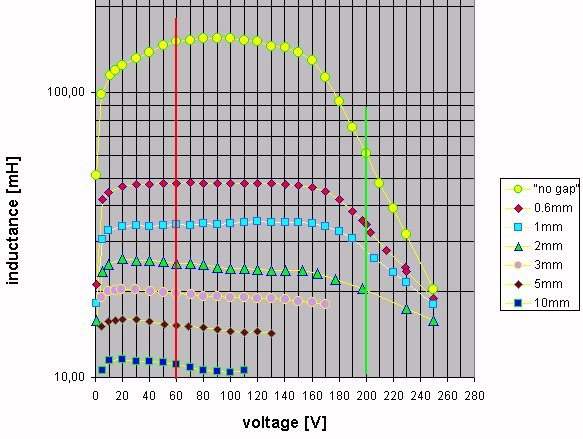
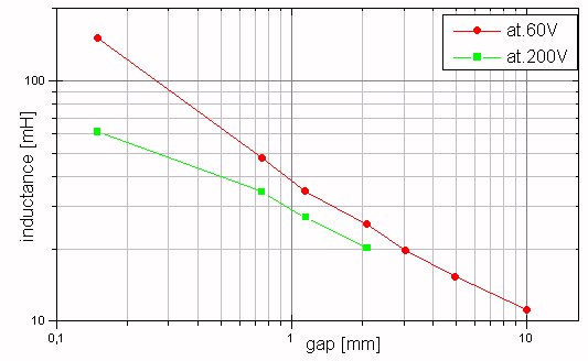
To make a long story short: I'm very satisfied with the results. I can vary
the inductance between 65mH (0.45mm gap) and 0.9mH if I remove the
"I" part of the core completey. With "no gap", the inductance
is about 144mH (in fact this is an effective gap of approx. 0.15mm), 48mH
with 0.75mm, 35mH with 1.15mm and 24mH with 2.15mm. With a gap of 0.75mm,
the iron core of the ballast inductor begins to saturate at 170V (inductance
drops at voltages above 170V). If the gap is set to 2mm, the current is limited
to about 30A.
The DC-resistance of the winding (48m of 6mm2 solid copper wire)
is 0.14Ohm, weight of winding (including perspex and tape) 3.1kg, weight
of core (the "E" and the "I" part together) 13kg.
Due to the low DC-resistance of the coil, the copper losses only will be
36W at 16A (136W at 30A), so the beast (yeah, if you ever have heard an xfmr
at 12A with the iron laminations not clamped together and the
"I" part of the core only loosely set on top of the
"E" part, you'll understand why I call it a beast :-))
should stay absolutely cool (at least the winding itself, some eddy current
losses surely will heat the iron core a bit).
My inductive ballast is buildt from 6 layers 18 turns each for a total of
108 turns 6mm2 copper wire around the center leg of an
EI-core with 47cm2 (7.3 square inch) cross section
area. Following the design criteria of Richies commercial buildt inductor,
I had to wind 148 turns for 250V. But commercial buildt units are usually
a bit overrated and I want to use an additional resistive ballast in series
which will have an additional voltage drop. Measurements have shown that
the core saturation is not really a problem (NO run away phenomenon!), its
just a non-linearity. So my inductive ballast works fine the way I buildt
it.
complete technical data of my inductive ballast1:
EI-core, weight 13kg
Why I made a second inductive ballast? Well, I achieved very satisfying results with my inductive ballast #1 and I wanted to be able to switch between them to adjust the current limiting by a simply turning a knob (rotary switch). OK, an arc welder would do the job, too, but arc welders are usually not designed for the current I like to pump throught the ballast in the future so they would be prone to overheating. I decided to make a sophisticated circuit to use the two ballasts either in parallel or in series or only one of them at a time, so I'll be able to limit the current to 7.5A (both inductive ballasts in series), to 15A (only the big ballast#1) and to 30A (both in parallel). This required a rotary switch consisting of at least 3 positions (4 if you want to have an additional "off" position) and four layers. You will need two layers with one "connect" (and the other three "open") contact and the other two layers with the reverse logic (three "connect" and one "open"). Most switches will only provide "one connect and the other open" contacts, but you can use two contactors to invert two layers (but be careful: from the safety point of view, the "off" position is not safe any more as one contactor could fail and let loose so it will make contact). You can find a circuit diagram of the rotary switch on my BlueThunder-page.
Ok, now on to the technical details of my inductive ballast #2: I 'recycled'
two old 765VA-xfmr cores and combined them to one big UI-core
which now has a core area of 30cm2 (cross section was two times
40mm x 38mm). It was wound with 3mm2 isolated stranded
wire (doubled 1.5mm2, much easier for my fingers than the solid
6mm2!) for 15A continious at max. 250V.
complete technical data of my inductive ballast2:
UI-core, cross section: 30 cm2

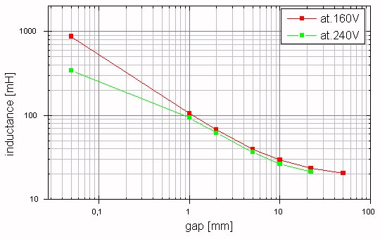
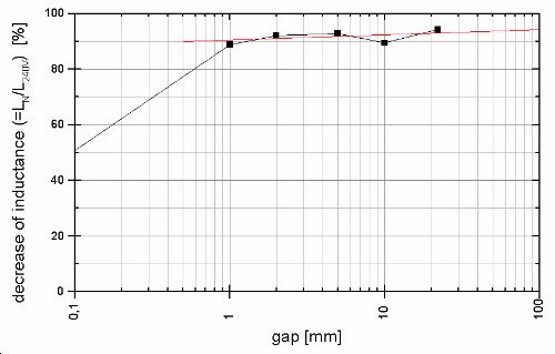
As can be seen from the last diagram, saturation is not a problem for a gap wider than 1mm (inductance decrease less than 10% at 240V compared to the nominal value). This is a significant improvement over ballast#1 as can be seen in the section before.
Inductive ballast #3 and #4:
I got more pigs, so I need more ballasts. The inductive ballast#3 is
already wound ("Hagmeyer-core"), still have to make the
diagrams.![]()
Inductive ballast#4 is planned to be wound on a core from my coiling friend
Kurt Schraner.![]()
Inductive ballast #5:
I got a nice fat ferrite core on a hamfest in Attaching in 2006, which is good for kW (at least the seller said this). It is made from N27 (max. flux: 300mT) which should be good up to 50(100)kHz. Core area is approx. 200mm. at the moment there are approx. 65 turns of 4mm diameter (12mm2) copper wire on it. Airgap is set to 12mm, minimum airgap will be 7mm if I can get the spacers out (glued to the core). I don't know if this setup is suitable for 230V at 50Hz as it is, measurements still have to be done.
![]()
After I buildt the first two inductive
ballasts, I collected some info on saturable reactors (did an
altavista-search). From what I have read so far, it seems possible to me
to build one of these devices (Finn already has buildt a prototype). Perhaps
I'll do so, perhaps not, but at least I wanted to give you the hint... Be
sure to build the type which will limit the current when the control voltage
is OFF (safety reasons)! BTW, Finn and Martin described two examples on the
GTL, read the thread from about 4.10.00-8.10.00. I'll place
more on this subject here when time
permits.![]()
You can find a description from another coiler at
http://personal.bellsouth.net/j/o/johngd/files/neon/saturable_reactor/
These are photos of a saturable reactor used to control the power to a
neon plant bombarder. The large center winding is the DC control winding.
The two outer windings are the current windings, designed in this case to
handle 60 amps. They are wound magnetically additive so that their
fields travel around the outside of the core and do not penetrate the control
leg. DC applied to the control winding adds flux to both control leg
cores, enough to saturate them. As the core saturates, the inductance of
the coils drop and pass more current. When the core is fully saturated, the
current is limited only by the DC resistance of the windings and the external
series load. The small white winding visible in Photo 3 is a test
winding I put on the core to measure the turns of each winding. A
small amount of AC from a variac is applied to each winding and the voltage
induced in the test winding is measured. Since I know the nubmer of turns
of the test winding and I know the applied voltage, it is a simple
matter of computing the ratio to determine the number of windings on each
leg.

![]()
![]()