How to build the perfect secondary coil
![]()
![]()
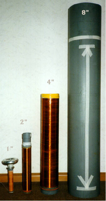 |
These are the secondaries I buildt up to now. Well - actually I buildt one more: the twin for Vitamini. And the BIG 8"-coil still has to be wound some day (the winding length has changed as I got a 4.2kg-spool of 0.8mm-wire recently which I will use now instead of the planned 0.63mm one) Update: I will build a 25*125cm coil instead of the depicted 20*109cm coil! In all of my coils I followed more or less the instructions given by the text below. I never had one coil failed up to now. So I think it is a good design guide. Until you have a good reason not to buildt a coil like described below, you should do it this way. *) please take a look at the bottom of this page for my (STK) personal oppinion on coil size vs. input power |
awg = 1 + [ log( 7.348e-3 / wd ) / 0.115943 ]
awg = American Wire Gauge,
wd = wire diameter
| AWG | mm |
| 38 | 0.1 |
| 34 | 0.15 |
| 30 | 0.25 |
| 24 | 0.5 |
| 22 | 0.63 |
| 20 | 0.8 |
The data is only for rough calculations since he real diameter will depend on the thickness and number of insulation layers! Here is diagram with the data points based on the data in the program "TESLAC":

(see also http://www.askjanfirst.com/kd/AWG.pdf)
Text file for COILBLD1.GIF, graphical instructions for construction of high performance 1/4 wave Tesla resonators.
1) The first step in winding a coil is to select a coil form. The coil form should be a low loss material (we are talking about radio frequency losses in the 50 - 1000 kHz range) like polyethylene, polystyrene, or polypropylene, polycarbonate (Lexan), acrylic (Plexiglas), or even ABS: but the most common material used from the standpoint of cost and availability is PVC (poly-vinyl-chloride), which is VERY HIGH LOSS. PVC may be used if the material is properly prepared before winding on wire. Regardless of the material selected, the thinnest possible coil form should be used; avoid heavy walled or pressure rated tubing.
The ratio between the actual winding length and diameter is important. The
ratio of the winding length to the winding diameter is known as the ASPECT
RATIO (height : diameter), where the diameter always equals 1. Aspect ratios
may be expressed by a single number such as "3.21". Please review the simple
chart below when selecting a coil form and the proper wire gauge: (All dimensions
are in U.S.A. measurements, inches, feet, AWG, etc..)
| Coil Form Diameter | Aspect Ratio | Winding Length |
| 3 inches | 6:1 | 18 inches |
| 4 inches | 5:1 | 20 inches |
| 5 inches | 4.5:1 | 22.5 inches |
| 6 inches | 4:1 | 24 inches |
| 7 inches | 3.5:1 | 24.5 inches |
| 8 inches | 3:1 | 24 inches |
| larger than 8 inches | 3:1 | multiply the coil diam. by 3 |
| *) please take a look at the bottom of this page for my (STK) personal oppinion on this table | ||
This chart is based upon the physical characteristics of the actual winding. Do not assume that "six inch PVC drain pipe" actually measures six inches o.d., and be sure to allow a few inches of extra coil form length. When selecting and cutting the coil form you should allow at least an extra inch of coil form on each end, and I generally figure on cutting the coil form three inches longer than the actual winding length. After determining the length of the coil form required, measure twice, then cut. Make sure that both cut ends are square.
2) The coil form must be free of major surface imperfections. I wet sand my coil forms with #150 wet/dry sandpaper (or emory cloth) and water to remove markings, oxidation, scratches and cuts. After wet sanding, the coil form must be dried thoroughly. If PVC plastic is used the coil form should be dried in a drying box, gently baked under a heat lamp, or even placed in a very low temperature oven for a few days. PVC coil forms must then be sealed to negate the high RF loss factors that are inherent to this plastic. Sealing also prevents PVC plastic from reabsorbing moisture. Using a sealer such as petroleum based polyurethane varnish, two-part clear epoxy paint, and some acrylic spray sealers is important. Avoid water based and milky "emulsion" type sealers.
When I am ready to seal a PVC coil form, I mount the form up on a winding spindle. I work in a well ventilated area, and I turn on at least one fan to keep air moving over the work. I set up a few heat lamps or other spark-free radiant heat source. Then I begin a four hour coating process. I prefer a high-gloss polyurethane or epoxy sealer applied with a good varnish brush. Sealer is slopped on while the coil form is spun. I use the brush to apply and smooth the heavy coats, and to spread out drips and runs. Coats may be applied almost continuously in this fashion for an hour or two. After coating the coil form, it should be rotated on the winding spindle for a few hours while radiant heat and moving air are used to speed a cure. Using this method it is possible to build up a high-gloss finish which is free of runs, drips, and sags. If drips and sags do occur, then can be "grated" off with a body putty grater, or carefully trimmed away with a knife while the sealant is still pliable.
3) The coil should be close wound with a good quality magnet wire. I use double Formvar enamel coated magnet wire purchased surplus, but newer insulations such as Polyimide coatings are even better. Magnet wire gives the maximum inductance per unit volume of coil form. The coil should have over 800 turns, but not too many over 1000 turns. There is a little leeway here. Use the thickest gauge of magnet wire that will allow the correct aspect ratio, and between 800 - 1000 turns. It has been suggested that all coils be wound with at least No. 22 AWG, or larger, magnet wire. I would concur with this recommendation.
I plug the ends of the coil form with a tight fitting wooden disk and run a dowel or threaded rod through a center hole so that it will spin. I set up the wire spool so that it will spin at one end of a pair of sawhorses, with the coil form at the other end. I wind the wire on by hand, making sure the windings are close-wound, tight, smooth, and even. Overlaps and gaps will adversely affect the performance. I use a dab of hot glue, epoxy, or tape to hold the first turns in place, and I make sure to leave a 3 foot tail of wire at both ends. Do not drill holes or permanently route wire inside of the coil form.

ROUGH FREQUENCY CALCULATIONS:
Assuming the information given in the text and chart above is used, a rough calculation of the resonate frequency (note by STK: please take into account that the given frequency will be lowered down to 80% or even down to 50% of the given value by using a sufficient large top load!) is given below. In the chart below:
OD = outside diameter in inches,
Wire Gauge is in AWG,
TPI = turns per inch,
Turns = total number of turns of wire on the coil,
Resonate Frequency is given in kilohertz and the figure is approximate
only.
| Coil Form OD | Wire Gauge | TPI | Turns | Resonate Freq. |
| 3 | 22 | 37 | 666 | 840 kHz |
| 4 | 22 | 37 | 740 | 540 kHz |
| 5 | 22 | 37 | 832 | 380 kHz |
| 6 | 22 | 37 | 888 | 290 kHz |
| 7 | 22 | 37 | 906 | 238 kHz |
| 8 | 22 | 37 | 888 | 206 kHz |
| 9 | 22 | 37 | 999 | 163 kHz |
| 10 | 21 | 32 | 960 | 152 kHz |
| *) please take a look at the bottom of this page for my (STK) personal oppinion on this table | ||||
You can see by reading through the text and looking at the charts that some design problems occur in coils with a small outside diameter. Coils under five inches in diameter must make sacrifices: either they must get long and skinny to obtain a sufficient number of turns; or they must be wound with smaller diameter wire. When making this decision, after determining that a larger diameter coil will not be satisfactory, it must be understood that 75% of the voltage produced by a 1/4 wave Tesla secondary results from pure resonance; meaning that the "ratio of turns transformation" calculated with the primary coil is not responsible for the majority of voltage gains: go with heavier wire as I have indicated rather than additional turns. On small diameter coils the aspect ratio may be increased somewhat rather than sacrifice turns or wire diameter.
A short remark from me (STK) on voltage gain: I don't agree with Richard here because energy preservation is also valid on Tesla coils! This means the energy stored in the primary tank cap is always higher (losses!) than the energy stored in the secondary's selfcapacitance and topload. There is NO accumulation between the individual bangs, because the secondary is "dead" for "99%" of time!!!
COILBLD-series 6/7/95 Graphics and text prepared by:
Richard T. Quick II <richard.quick@slug.org>
10028 Manchester Rd
Suite 253
Glendale MO 63122 USA
Question:
> How would someone go about drying a PVC or similarly hygroscopic material before it was to be sealed? In the oven? What temp? Is the interior of the form sealed as well?
Answer (RTQII ?):
Before I get to the drying stage, I go ahead and wet sand the coil form with abrasive paper or emory cloth. I use a #150 grade of abrasive and sand with water until all printing, oxidation, and major dings (cuts and scratches) are removed.
One of the best ways to dry this plastic is to get a large cardboard box. Cut a few small vent holes in the top and bottom of the box. Thread some string or light cord through the top of the box to form a sling to hold the coil form. You will need two or three loops of cord inside the box to securely suspend the coil form near the top vent holes.
Place a light bulb on a heat resistant insulator inside the box directly below the coil form. Depending on the ambient temperature, the size of the box, and the number of vent holes, the wattage (or number) of bulbs may be varied.
The heat from the bulb(s) will produce a warm air convection inside of the box that will effectively dry the coil form over a period of no more than three days. The temperature does not need to be very high, temperatures between 120 - 150 degrees F are just fine.
Once removed from the drying box, the outside of the coil form should be sealed immediately, then wound with wire. Once the coil form is wound, the ends of the coil form are capped with plastic disks glued down with epoxy to form a hermetic seal.
However, if the coil form is removed from the drying box and winding is delayed for some reason, one coat of sealer should be applied to the inside of the coil form to prevent moisture from reabsorbing. If the winding proceeds at an orderly pace without delays, then the end caps will prevent air exchanges which removes the need to seal the inside surface of the coil form.
My (STK) personal opinion: PVC is as good as any other type of modern plastic. Besides a vacuum impregnation, there is no way to exclude moisture from the coil form. But I think that this tiny bit of moisture is NOT important for performance because the electric field lines are perpendicular through the coil form and therefore only a very small fraction of the length of the field lines interact with the form material and the absorbed moisture (wall thickness compared to total arc length).
Question:
> Besides polyurethane what is a good sealer for a secondary coil form and and where do I get this sealer?
Quoting Chip Atkinson:
The coating that I used is called Super Gloss Build 50 by Behr.
I got it at the hardware store. (Hugh M. Woods, aka Payless Cashways) It is in two paint cans, shrink wrapped together. The can wrappers are orange. The stuff is stocked in the varnish section, right next to the polyurethane. The potential problems are bubbles, which didn't seem to make much of a difference for me, and annular bulges. The bulges appear if you don't get the coating on evenly and the form is turning. I would not recommend using Build 50 as a coating unless you feel confident in your abilities to apply it smoothly and evenly. I ended up with some bulging, but it doesn't detract from the over all appearance. It would however cause problems if one used it to seal a PVC pipe under the winding. This would make the windings irregular and probably cause the top coat to be very uneven as the stuff bulges and climb towards the high spots as the form turns. Nevertheless, I still recommend Build 50 since it goes on in one coat and is quite tough and hard. Chip Atkinson
> I got the 8" PVC today. Cost me $7.00 for 3 feet. It is solid wall about 5/16" thick. I am going to setup something to dry it later today. I got a basic polyurethane varnish to coat it with.
No problems here. The coil form could be thinner walled. I always try to use the thinnest walled material possible for my coil forms.
> You said you did not want to put any holes on the coil form if necessary because of moisture seeping in. What about throwing a couple packets of silica gel in before sealing it up? Or maybe some other dessicant?
Holes in the coil form are avoided primarily because holes compromise the electrical strength of the construction. The fact that a properly sealed and capped secondary coil prevents re-absorbtion of moisture when using properly dried and prepared PVC is an added bonus. Desiccants such as calcium sulfate, silica gel, etc. will simply trap water. I would not use these desiccants with the idea that these compounds are going to end up as permanent parts of the coil. Desiccants can be employed as part of the drying process if desired, but these compounds should be removed (along with any absorbed moisture) and not left as part of the sealed construction.
> Oh, how did you cut the plexiglas disks in a circle?
I use a band saw or a jig saw. A plastics dealer will be able to custom cut these disks if required, and the same plastics dealer is usually able to supply the correct blades and cutting advice if you ask.
> And what about using a Silicon RTV type cement to attach the ends. This stuff is deffinitly non-flamable and is hard to screw-up with.
Good Question! Sounds great does it not..? But... These adhesives leave a residual acetic acid vapor which is trapped in the coil form. The acetic acid vapor is highly conductive and ionizes readily. DO NOT USE THESE PRODUCTS in this particular application.
> I am also going to order the wire today. What gauge should I use?
I would used about 888 turns of number 22 AWG enameled magnet wire. You will need about 3.75 pounds of wire to complete this project, so, figure on buying four pounds of No. 22 AWG enamel covered magnet wire.
> A brief suggestion regarding polystyrene as a form material: it is polystyrene as is the plastic used to make model cars. Why not use airplane glue? It will act as a solvent welding activator, is very water and humidity resistant, and if used properly, will resist at least the same temperatures as the form material? I have no idea what the electrical properties are, but it is cheap and possibly worth a try.
I am not exactly sure what you propose using airplane glue for, but I can tell you from experience, you don't want to use this material anywhere on or near a Tesla coil. The bottle is clearly labeled "DO NOT USE NEAR SPARK OR FLAME".
If you were to use a solvent based adhesive to cap the ends of the secondary coil form for instance, and the coil fails internally, the resulting explosion will be hazardous. Trapped solvent fumes mixed with air in a sealed tube provides enough energy for a pretty decent explosion. I have had this happen more than once. The windings will prevent the entire coil form from splitting, but the ends of the coil form between the winding and the cap will shred and throw shards of coil form "shrapnel" about the room. The discharge terminal will be thrown, and you can almost count that it will receive damage when it strikes the floor or the tank circuit. Nowhere in my instructions do I recommend using solvent based adhesives in the secondary coil construction.
I've just intercepted RQ's request for info on secondary coatings, and I thought I'd throw my info in here. In UK there is a component distributor called RS Components who supply all sorts of electronics gear. They have a number of products for HV insulation. I have got hold of a tin of the following
Anti Corona Lacquer 569-290 $2.86 400ml Aerosol
This has a dielectric strength of 48Kv/mm with a working temp of up to 150 degrees C. I intend to follow RQ's preparation and sealing method for secondary construction on a 4.5 inch Diameter Perspex (Lexan) former, but use this stuff instead of polyurethane.
Unfortunately the perspex has been extruded, not moulded, so there are small striations / lines running along the length of the tube. This is why I intend to wet & dry it before winding. Also being extruded, it is not completely round :( I have some 0.4 mm enammeled Cu winding wire and I have calculated 1150 turns with a 4:1 aspect ratio. On top of this goes my 12" x 3.5" stainless steel toroid. I have just had this shotblasted and it is double sexy. I have silver soldered a 1/16" thick circular steel plate into the centre of this to support the toroid while on top of the coil. I have asked this before, but I can't remember if I got an answer. When constructing the secondary coil, I seem to recall that RQ recommends sealing end caps on the former. Why is this?
Anyway, back to the point in question. There are some more products of interest in the same section of the RS book:
modified silicone conformal coating
90Kv/mm dielectric strength
red and transparent colours
fluoresces under UV (good for tracing corona leakage?)
temperature -70 - 200°C
best cure 24 hours @ 100C; 200ml aerosol 494-714 $6.20
--------------------
Tropicalised varnish
Acrylic varnish with UV tracer
touch dry in 10 mins
recommended drying 24 hours @ 21C + 4 hours @ 60°C
temp -60 - 130°C
dielectric constant 2-45 @ 10KHz @ 21°C
dissipation factor 0.028 @ 10kHz @ 21°C
500ml tin 188-627 $6.29
-----------------------
Hope this info is of use. As I say this is a UK source but no doubt there are equivalents in USA. Prices are in pounds sterling but I can't make my keyboard do Pound signs. Cultural imperialism or what?
Quoting Steve with ">"
> I have asked this before, but I can't remember if I got an answer. When
constructing the secondary coil, I seem to recall that RQ recommends sealing
end caps on the former. Why is this?
In a high performance design, properly driven, the secondary coil is easily capable of producing sparks that greatly exceed the physical height of the secondary coil. In other words, your coil may be 20 inches tall producing sparks that are 30 inches long.
Under these conditions an "open" or uncapped coil will almost certainly fail. All of the electrical failures that I have seen occurred inside of the coil form. The failures resulted in sidewall perforations, arc scoring, and carbonization of the coil form. I have never been able to successfully repair a coil once it has failed in this manner.
To prevent electrical breakdowns in the secondary coil the following points are important:
If these simple guidelines are met, the coil will have an enormous electrical strength and failure is highly unlikely. Coils wound on all plastic coil forms that are constructed following the simple guidelines above can produce sparks that exceed the physical winding height by a factor of 5 to 1 without failure or breakdown in the construction.
Every set of printed coil plans that I have seen shows two holes drilled into the coil form sidewall. The wire used to wind the coil is fed through the hole near the intended base. The wire is then routed inside of the coil form to a ground terminal. The coil is wound, and the other end of the wire is fed through the hole near the intended top. The wire is again routed inside of the coil form through an insulator mounted on the top of the coil. If end caps are even used, wood is frequently recommended.
While these instructions will work fine on an open wooden or cardboard coil form that is space wound with d.c.c. (double cotton covered) wire a-la 50 years ago, if followed today using close wound magnet wire on a high-Q plastic form it is lethal.
Modern high-Q construction materials demand a change in construction practices and techniques. A high inductance design (close wound magnet wire on a plastic coil form) will produce a very potent secondary winding which will promptly smoke when coupled to an efficient tank circuit unless care is taken to prevent internal arcing and sidewall failure of the coil form. If the wire is never allowed to enter inside of the coil form, no holes are drilled into the sidewalls, and both ends of the coil form are properly capped, there is no way the spark can get inside of the coil. The result is that the coil will not fail.
BTW, the reason I have recommended that solvent based adhesives NOT be used when capping the coil form is because the explosive vapors are trapped inside of the coil. If points #1-3 are followed then point #4 should not be too critical, but if an internal failure of the secondary coil does occur, you can count on any trapped vapors igniting and an explosion will result. This is not just an idle warning either. I have had it happen and it was nothing but dumb luck that a serious accident did not result.
> On the subject of coatings:
> Richard Hull (or TCBOR) mentions in the guide to the Colorado Springs
notes that he/they don't use secondary coatings anymore-or at least they
were using only a single thin coat. He says they avoid breakdown from the
coil by proper terminal placement. Any comments on Hull's method?
Yes, Hull's method works just fine. Many times I have test fired a coil with no coating whatsoever. While coating is not an absolute necessity, it is worthwhile for several reasons.
I guess the argument here is that if you are winding a coil to become part of a permanent system where changes are rarely or infrequently made (like a museum or display coil) one or two light coats of sealant, or just enough to stick the windings down, would be fine. Once tuned and adjusted with a proper toroid the coil will function well, and without excessive corona losses.
But on the other hand if you are like me; a person who frequently removes/replaces/stores coils, changes primary configurations, gaps, caps, dischargers, fires an occasional Magnifier or bipolar system, etc.. The benefits of a good heavy coating are clear, if for no other reason than protecting the winding from accidental physical abuse.
I have found that the benefits of a heavy coating on the secondary far outweigh the advantages of a light or nonexistent coating. Also, there are a lot of beginners out there. Beginners especially need the physical and electrical ruggedness that a heavy coating provides.
Text file for COILBLD2.GIF, graphical instructions for construction of high performance 1/4 wave Tesla resonators.
4) Once the coil is wound, it is sealed to prevent corona leakage and to help protect against electrical breakdown between turns. Sealing also prevents the windings from loosening up on the coil form. I use the same sealers mentioned earlier, those being petroleum based polyurethane, two-part clear epoxy paint, or water free acrylic. Coats of sealer are applied with a brush or spray until there are no ridges and valleys in the wire. In other words the coats must build up until the wire is completely imbedded in sealer. A fan and radiant heat source may be used as required to speed the cure rate of the sealer. Rotating the coil on the winding spindle will aid in obtaining a smooth coating that is free of runs and drips.
5) Two plastic disks are cut to match the ends of the coil form. The plastic should be approximately the same thickness as the coil form walls. Experience shows that plexiglas is both readily available and works quite well in this application. Dry fit and file the caps as necessary until a good match is made to the coil form ends. I rough up, or score, the matching surface of the plastic disks where they will be bonded to the ends of the coil form. This provides a surface around the edges to give the epoxy adhesive a bite.
6) Make sure all surfaces are dry, clean, and free of oil. Place a bead of fresh, good quality, clear two-part epoxy adhesive around the top of the coil form and the matching end cap, then cap the end of the coil with the plastic disk. Weight the end cap down until the epoxy has cured; then flip the coil over and repeat the procedure to cap the other end. I will stop here to make an important note:
NO HOLES ARE EVER DRILLED INTO THE SIDEWALL OF THE COIL FORM!
WIRE IS NEVER ALLOWED TO ENTER INSIDE OF THE COIL!
Ideally the secondary coil should be hermetically sealed. This prevents internal electrical breakdowns of the coil and prevents the uptake of moisture into the coil form when PVC plastic pipe is used. If holes are drilled into the coil sidewalls, and/or, the wire is allowed to enter inside of the coil, then spark lengths that exceed the length of the winding will almost surely cause the coil to fail. Once a coil has failed in this manner it is not repairable. One small hole may be drilled into the bottom end plate to allow the air pressure to equalize, but under no circumstances should any other holes be drilled.
Text file for COILBLD3.GIF, graphical instructions for construction of high performance 1/4 wave Tesla resonators.
This series of diagrams shows details of the coil base and the steps required to construct a high current ground terminal without drilling into the coil form or permanently mounting protruding hardware.
7) The first step in constructing a high current ground terminal is to cut out a rectangle in the sealer at the base of the coil form just below the winding. The coil winding should end just above one corner of scribed area. The cut should be about two inches long and one inch high, minimum. This section of sealer is then peeled and scraped away to expose the bare plastic coil form. Use a blade and deeply score and cut the bared plastic in a "cross-hatch" pattern.
8) Cut a strip of copper from some heavy copper sheet. The strip of copper should fit inside of, and almost fill, the cleared and scored area on the coil base. Round the corners of the copper strip, then bend the strip gently until it conforms exactly to the curvature of the coil form. The rounded and curved strip of copper should fit neatly on the coil form in the prepared area. If copper sheet is not available the ground terminal may be constructed by splitting open a section of copper water pipe and peening out the proper shaped terminal.
9) This next step requires a piece of steel (with a flat surface) and a small hammer. Gently pull the base wire of the coil free from the sealer. Pull the wire up all the way to the beginning of the winding. Once freed, trim this wire, leaving a 2-1/2 inch length. Scrap the base wire clean of all sealer and enamel insulation. Next, carefully wrap some heavy plastic or cardboard around the coil to protect the winding from dings, but leave the base wire extended and exposed. Position the coil so that the base wire may be laid out flat on a small steel block or plate, then gently peen the wire out with a small hammer. Copper wire is very malleable, it will be possible to peen the round wire into a thin flat strip. Trim the length again if required.
10) Clean and tin the inside curved surface of the copper strip. Clean and tin the peened out base wire from the coil. Using a clothes-pin, or other small clamp, position the flattened base wire diagonally across the inside curve of the copper strip. Solder the two together with a very hot iron. Avoid clumps or blobs of excess solder. Clean the soldered area thoroughly with solvent to remove all traces of rosin, oil, and dirt. Sand the soldered area gently with abrasive paper to smooth out any rough areas and high spots. Clean the soldered area a second time.
11) Using a cloth or lint-free wipe, clean the scored rectangle on the coil form base with solvent, carefully removing all traces of oil and dirt. Wipe down the copper ground terminal one last time. Prepare some strips of waxed paper and an assortment of rubber bands. Mix up a small batch of clear, two-part epoxy. Smear the scored rectangle on the coil form with epoxy, then smear the inside curve of the copper ground terminal. Fit the ground terminal into place, cover with strips of wax paper, and secure with a couple of rubber bands around the coil form. Allow sufficient time for the epoxy to gel firmly, but do not allow a complete cure. Remove the rubber bands and the wax paper strips. Gently scrape away excess epoxy from the surface of copper ground terminal, then wipe the terminal surface clean with solvent. If attention has been paid to detail and technique, the copper ground plate should be nearly flush and firmly attached to the bottom of the coil form just below the winding. Sometimes it may be necessary to fill in a low spot or two with a second tiny batch of epoxy.
12) This figure shows how effective this ground terminal is in practice. It is quite easy to connect one inch SMOOTH grounding strap directly to the base of the coil with a couple of rubber bands or a long strip of electrical tape. This connection is ideal for removing the heavy RF current produced at the base of the coil. This ground terminal is also nice in that it may be quickly connected and disconnected, offering flexibility and ease of setup. This system is also efficient if the base terminal is to be used to feed RF current into the bottom of the coil, as in the extra coil of the Tesla Magnifier.
Being flush mounted without drilling holes into the coil form, this terminal preserves the electrical strength of a sealed coil form. Without protuberances typical of other terminal types, there is nothing to break off or damage. The same lack of protuberances makes it easy to store several coils close together without worry of scratching or cutting the finishes. This terminal is clean and professional looking.
Text file for COILBLD4.GIF, graphical instructions for construction of high performance 1/4 wave Tesla resonators.
13) If the preceding directions have been adhered to, the completed Tesla coil (RF resonator) will closely resemble the diagram in figure 13. The coil form is hermetically sealed. There are no holes into the wall of the coil form. The wire never enters inside of the coil and all connections are made externally where they do not compromise the electrical integrity of the construction. The base wire has been cut, peened, and connected to a high current ground terminal. The other end of the coil, the air terminal, has been left untrimmed.
14) This shows how the air and ground connections are made to the completed coil. A stand-off insulator is placed on the top of the coil. A TOROID discharge terminal is placed on the insulator and the wire is air-wound around until it contacts with the bottom plate of the conductive toroid. These air wound turns are widely spaced, but the diameter is kept as close as possible to that of the secondary winding. Once contact has been made to the bottom of the toroid, the wire may be held in place with a small piece of tape, then the winding is discontinued and a bared section of wire is connected directly to the center of the toriod with a nut and bolt clamp, tape, etc.. Excess length may now be trimmed.
The exact length of the stand-off insulator, and therefore the height the toroid discharge terminal sits above the secondary resonator, can only be determined by experiment. This varies with the size of the toroid, the size of the coil, and the input power into the system. Due to the number of factors involved, this insulator may require frequent adjustments/changes. For this reason I do not permanently mount a stand-off insulator on the coil. I keep a selection of square cut sections of PVC plastic pipe that I use for stand-off insulators. The toroid is electrically connected as indicated above, then it is simply set on top of a PVC pipe stand-off insulator. The system is now ready to be fired. If desired, after some experimentation, the insulator can be permanently mounted: the end cap should be scored with a sharp tool, not drilled; the surface should be prepared, and the insulator should be glued in place with two-part epoxy. The ground connection is made via the shortest available path, using the heaviest, widest possible SMOOTH conductor, to a dedicated RF ground constructed specifically for Tesla work. This ground is referred to as the "system RF ground" or simply the "system ground". The system ground is usually constructed, not happened upon. I advise constructing a system ground from scratch unless you can verify that any available grounds are electrically isolated. Do not use a water pipe. Do not use the house ground. Tesla rated grounds need to be extremely heavy, usually comprising of several eight to ten foot copper pipes hammered into the ground. The pipes should be separated in the ground by their lengths (eight foot pipes are set eight feet apart) and connected with one inch ground strap buried below sod level.
It should be noted that these instructions are designed to produce a highly efficient RF resonator with exceptional electrical strength at the lowest possible cost. Coils built to these specifications are capable of producing, and withstanding, discharge lengths that exceed the physical length of the coil by a factor of 3.5 or more. These instructions are the product of years of experimentation winding dozens and dozens of coils and with the collaboration of others in the field of high powered Tesla systems. This design method has been repeatedly tested and reproduced by beginners with excellent results.
Richard T. Quick II <richard.quick@slug.org>
10028 Manchester Rd
Suite 253
Glendale MO 63122 USA
From my (STK) own personal experiences with different coils (1", 2", 4",
planned 10") I want to present a new table which is based on the new approach
that a topload pratically can NEVER be to big. Richard Hull demonstrated
this first with his giant toploads on his magnifiers (i.e. maggy 11E). The
bigger capacitance reduces the voltage on the toroid (because of energy
preservation), but the sparks will be longer despite this fact. When it comes
to max a coil out, one should not only use one big main discharge toroid,
but a smaller anti corona ring (ACR) below it, too. Why? Well, for small
input power there will be no problem. But I bet you would like to squeeze
the best out of your coil. Then you'll get problems with corona from the
top turns if the main discharge toroid is to far away from the coil. If you
only use one toroid and set it in a small distance onto your coil, then you'll
create eddy currents in it and the inductance of the coil will be lowered
therefore. The capacitance is decreased also and the overall performance
will be poor. (Perhaps one should make a slit in the toroid
and join the ends with insulating material! I still have to try this
approach...)
The best method is to use a small anti corona ring (ACR) with mean diameter
approx. 1.5x up to 2x the coil diameter in a distance of approx. the coil
diameter above the top turns. The exact position has to be found by experiment.
Then above this small toroid comes the standoff for the main discharge toroid.
A cone is an excellent shape for the best mechanical stability (Tupperware
is ok but looks really awful on top of a coil :-) The higher you set the
main toroid, the better your coil will perfom if you still can control the
unwanted downward strikes. Oh, yes, that is the second reason to shoot for
the two-toroid approach. Because of the better E-field shaping, the tendency
to strike downward into the primary coil is extremely reduced!!!
All in all, the optimum arrangement will look like this:
     _______________________________________________
   .'  .'    /      /       |       \      \    '.  '.
  /   /     /      |        |        |      \     \   \
 |   |     |       |        |        |       |     |   |
 |   |     |       |        |        |       |     |   |
  \   \     \      |        |        |      /     /   /
   '.__'.____\______\_______|_______/______/____.'__.'
                  \                   /
                    \               /
                    __\___________/_
                   / /  /   |   \ \ \
                   \_\__\___|___/_/_/  _____
                       _|______|_         ^
                       |        |         |  as far as possible
                       |        |    _____v_ (eddy currents!)
                      :|        |:
                      :|        |:
                      :|        |:
                      :|        |:
                      :|        |:
                      :|        |:
                      :|        |:
|
The formula for one single (!) toroid is given on my toroid page. It's hard to give a general formula for the two-toroid approach because of the different ways you can arrange them and the different shapes of the cone (and whether this cone is conductive or not). Until I did some measurements by myself or any other coiler can provide me some data, I state that in a 'typical' two-toroid arrangement, the 'effective cord diameter' of the main discharge toroid is increased by a factor of approx. 1.3 for 'flat toroids'. Additionally, I add some extra capacitance to Cself (sheet capacitance) because of the virtually increased winding length (typically about 2 times the coil diameter). Your opinion and measurements on this are welcome!!
Remember: you NEVER can have to much top capacitance! The only thing that can happen is that the 'thickness' (radius of curvature) of the toroid is to high to achieve breakout. But that is not really a problem as you can always add a bump. In this case, you have full control over the breakout (by the size and location of the bump), a very desirable situation. For my BIG 10"-coil (up to 5kW) I plan to use a 50"x6" toroid or even up to 58"x10". I already cut the 95cm diameter centerplate out of the green styrofoam stuff (but I might have to make it a bit smaller so that it will fit into my car :'-(.
Here is a table with some typical coil parameters (based on the tables given by RTQII above, the discussions on some mailing lists and my own experiences). As you can see, the aspect ratio is rised to 4:1 to 5:1 for all coils instead going down to 3:1 for big coils as suggested by RTQII. I've increased the number of turns in my table because of the lower voltage usually used here in Germany (low voltage => big tank caps => need to compensate this on the secondary side). This compensation cannot be done up to the optimum value on 'small' coils because the higher frequency of these coils requires bigger wire diameters (skin effect). The numbers should be changed now, because it seems that more turns (like 1500-2000) seems to produce longer sparks! As Paul Nicholson said: "for a disruptive coil, the secondary Q is of secondary importance. The potential advantage of increasing the inductance comes from the fact that for a given primary coupling factor, a larger primary inductance can be used, with possible consequent improvement of primary gap efficiency - a theory expounded by John Freau.".
| 'class' | coil form dia- meter |
wind- ing length |
wire dia- meter AWG / mm |
# of turns |
Cs [pF] |
L [mH] |
f0 [kHz] |
power [W] |
main discharge toroid |
Ct [pF] |
dCs w/ ACR [pF] |
dCt w/ ACR [pF] |
Ctot [pF] |
ftot [kHz] |
||
| min. | max. | D | d | |||||||||||||
| µTC | 1" | 4" | 38 / 0.1 |
980 | 1.83 | 5.37 | 1600 | 50 | 150 | 5" | 1.5" | 5.6 | ~0.5 | . | 7.9 | 1163 |
| MiniTC | 1.5" | 6" | 34 / 0.15 |
960 | 2.74 | 7.67 | 1100 | 100 | 250 | 8" | 2.5" | 9 | ~0.8 | . | 12.5 | 514 |
| 2" coil, table top |
2" | 10" | 30 / 0.25 |
980 | 4.11 | 8.88 | 830 | 200 | 800 | 14" | 3" | 15 | ~1 | ~1 | 21 | 369 |
| 4" coil, medium |
4" | 20" | 24 / 0.5 |
990 | 8.23 | 17.9 | 415 | 800 | 3000 | 25" | 5" | 27 | ~2 | ~1 | 38.2 | 224 |
| 6" coil, medium |
6" | 30" | 22 / 0.63 |
1175 | 12.34 | 38 | 232 | 1500 | 4000 | 40" | 8" | 43 | ~3 | ~2 | 60.3 | 105 |
| 8" coil, big |
8" | 40" | 20 / 0.8 |
1230 | 16.46 | 55.3 | 167 | 2000 | 10000 (???) |
50" | 10" | 54 | ~4 | ~2 | 76.5 | 77 |
Bigger coils are more efficient, that means you need less watts for the same sparklength. But in my opinion the sparklength should be at least the winding length to 'look cool'. I tend to max out every coil to get a real nice view (my goal is at least a spark length of 2 times the winding length, the more the better). Of course some variations can be made, most often in toroid size and wire diameter. As always: use what you have at hand if the values are not too far away from the specs given above.
![]() NEW
(8'00):
NEW
(8'00):
Skindepth in copper - what wire diameter is sufficient?
E:\CAPS\SKINEFFE.HTM ATTENTION: There are some mistakes in the formulas, I have to check them again!
Small coils have high frequencies (low skin depth) and low currents (small wire diameter required). Big coils have lower frequencies (higher skin depth) and high currents (big wire diameter required). But what diameter is sufficient? Well, the skin depth is the equivalent material thickness of an hollow cylinder with the same outer diameter(?) where 68% of the current flows. In two skin depths there is 95% of the current, in three skin depths 99%. So 2(-3) skin depths of radius seems to be sufficient, that means the wire diameter has not to be more than approx. 5 skin depths for CW-coils (TTTC, SSTC). For spark gap coils, the Q of the secondary is only important before breakout, so we can live with a wire which is much thinner!
Skin depth formula for cylindrical wires:
general behaviour: d ~ 1 / SQR(f)
exact formula: d=SQR(2/wxu) with w=2*Pi*f, x=electrical
conductivity,
u=Pi*4e-7![]()
simplified (for copper only!): d[mm] = 66.1 /
SQR(f[Hz])![]() beware: this formula is only valid for
d<<wire_diameter which is not the case here!
beware: this formula is only valid for
d<<wire_diameter which is not the case here!
Be careful: the skin depth in human bodies is about 40cm-2m!!! Even worse: the current flows along the blood vessels and nerves. Combined with the fact that nerves don't response to frequencies above some kHz, you can fry your nerves without noticing it. The output of Tesla coils can kill, please read the safety warnings!
Modifying the table given above I try to give the NEEDED wire diameter based on the frequency of the coil:
| coil form diameter |
wind- ing length |
wire diameter AWG / [mm] |
# of turns |
ftot [kHz] |
skin depth [mm] |
needed wire diameter [mm] = 3x skin depth |
needed wire diameter [mm] = 5x skin depth |
||
| 1" | 4" | 38 / 0.1 | 980 | 1163 | 0,06 | 0,18 | 0,31 | ||
| 1.5" | 6" | 34 / 0.15 | 960 | 514 | 0,09 | 0,28 | 0,46 | ||
| 2" | 10" | 30 / 0.25 | 980 | 369 | 0,11 | 0,33 | 0,54 | ||
| 4" | 20" | 24 / 0.5 | 990 | 224 | 0,14 | 0,42 | 0,70 | ||
| 6" | 30" | 22 / 0.63 | 1175 | 105 | 0,20 | 0,61 | 1,02 | ||
| 8" | 40" | 20 / 0.8 | 1230 | 77 | 0,24 | 0,71 | 1,19 |
![]()
| new ideas for the coil form (sorry, only in German
up to now, has to be reworked!):
AntiRacingSparkRings (kompletten Text auf die "secondary-page" bringen und von den 1", 2", 4", BIGcoil - Seiten aus verlinken!) Racing sparks brennen Löcher in die Isolierung, was spaeter meist zum Kurzschluss zwischen zwei Windungen am unteren Ende der Secondary fuehrt. Warum machen wir es eigentlich nicht alle so wie RWStephens und verwenden um die Secondary geklebte Ringe aus Isoliermaterial gegen die racing sparks? Ein Bild davon ist zu sehen unter: http://www.pupman.com/current/rstephens/mtc-a1.html Die Ringe wirken dadurch, dass sie den Weg der Funken auf der Oberflaeche verlaengern und dadurch gar nicht erst ein Funke entsteht (aehnlich den ueblichen Rippenisolatoren!) Klar, die meiste Zeit sind die Ringe ueberfluessig und machen die Secondary nur dicker. Aber "safety gap" und "strike rail" sind ja auch die meiste Zeit ueberfluessig wenn das System richtig designed wurde und haben sich trotzdem durchgesetzt! Berechnung im File: ARSR.xls: Beträgt der Aussendurchmesser der Ringe das 1.25fache des Spulendurchmesser, so sind bei einer 1.5fachen creepage path length und einem üblichen H/D=4 jeweils 8 Ringe nötig (unabhängig von der Spulengröße!) Größere Spulen sind eh schon unhandlich, hier wird man also mehrere kleine Ringe nehmen um einen kleineren Aussendurchmesser zu erreichen (z.B. 12St. bei 10", 15St. bei 12", 20St. bei 15"). Bei kleineren Spulen ist der Aussendurchmesser nicht problematisch, hier kommt man also mit weniger Ringen aus, die dann natürlich einen größeren Aussendurchmesser haben müssen (z.B. 7St. bei 5" und 4", 6St. bei 3", 5St. bei 2", 4St. bei 1"). |
![]()
![]()