Stefan's Tesla-Pages
My third solid state HV source
(output peak voltage 6.7kV)
again using a fly-back
transformer 
![[home]](buthome.jpg)

Table of contents:
-
Specs of the circuit
-
Photos
The specs of the third TV fly-back
system are:
-
Circuit
-
This circuit was extracted from a really huge CO2-LASER (1kW beam
power continious duty!) where it was the ignition circuit:
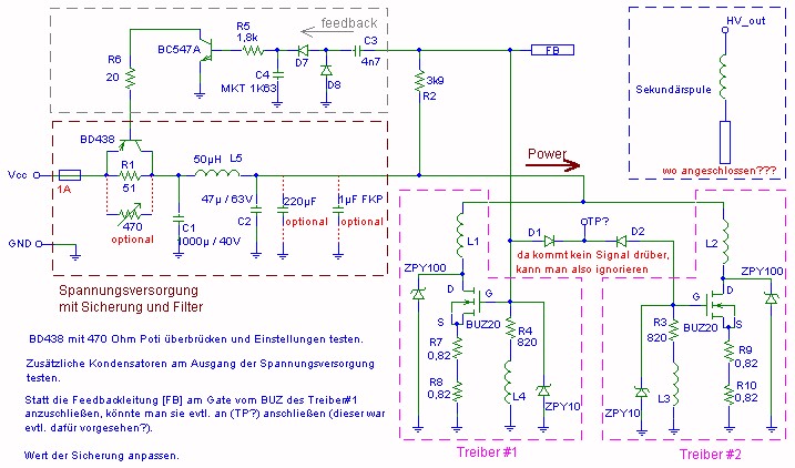
Sorry for the german text in the schematic,


    english version is coming soon after more detailled testing of the
    circuit!
-
-
-
-
Output is AC. The secondary coil is floating. The limiting factor in voltage
is the potential against the grounded ferrite core. Perhaps it would be a
good idea to connect the low voltage end of the secondary coil to the earth
lead of the power plug...
-
I have no idea what the initial driving voltage was. The circuit starts to
run at aproximately 14V. The input cap is rated 40V. Therefore I guess it
originally was designed to run at 24V. I made a DC source for 25V. When drawing
an ac, the power resistors R7-R10 get hot but not as much as to worry about.
The Heatsink of the transistors gets warm.
-
With the peak voltage rectifier I described
here, I measured the peak output voltage
to be 6.7kV (Vss=13.4kV, Veff=4.75kV assuming sinusoidal waveform).
-
With no arc, the input current (measured at the fuse) is 0.7A. With an arc
at the output, it increases up to 2.5A. Since it was not designed to
deliver a continious arc, the 1A fuse makes sense and the 24V driving voltage
seem to be ok.
-
I for sure want the circuit to deliver considerable output power. The only
parts which get hot at the moment are the BD438 and the four 0.82 Ohm power
resistors at the drivers.
-
Seems as if the purpose of the BD438 is to control the
power into the circuit. I want to maximize the power, so I'll try to bridge
the BD438 with a power-pot and see if I can increase the input current (while
an arc is drawn) by decreasing its resistance, hopefully down to zero Ohms.
If that works, I'll remove all connections of the feedback circuit (connection
FB from the gate of the BUZ20 and the 3.9k resistor).
-
Next step is to bridge the four 0.82 Ohm power resistors
at the drivers with an aditional power-pot. I'll decrease the value until
anything other than the power resistors will start to get hot.
-
Hopefully, adding some capacitors will improve the circuits
pulse capability (read: more output voltage). I plan to add 220uF to the
47uF in the input filter to adjust to the increased power level. A high
performance pulse capacitor (FKP or MKP with approx. 1uF) will be added to
get fast raising pulse edges.
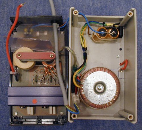
I finally managed to get the whole thing (WITH
the power supply) into its old housing:
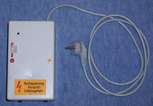
Here the housing is closed:
And here with a paper clip installed to make a miniature Jacobs ladder:
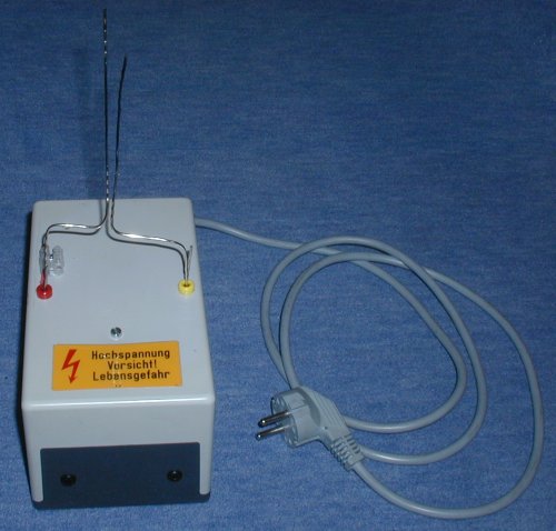
And now with some power applied:
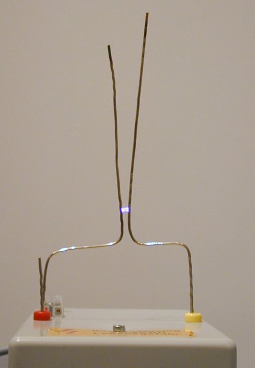
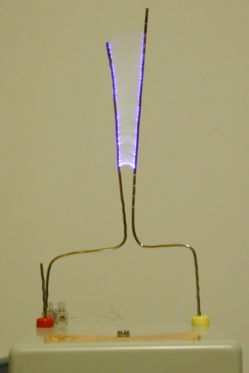
Here are two movie clips. the first one shows me starting the arc by sticking
some kind of metal tool between the rails, the second one using a lighter
(click the images):

Experiments, max. arcs etc.:
-
I got 120 caps 4.7nF@30kV and plan to build a villard cascade from them using
the ignition circuit above as the driver.
Charging the all caps (564nF) up to 20kV, the total energy in them will
be 113J (176J at 25kV).
-
some suitable diodes (suitable for the high frequency of the flyback circuit)
will be either KYX28/15 (15kV/2mA) like here
http://www.rapp-instruments.de/diverse/multiplier2/multiplier.htm
or Diotecs DD1800 (18kV/20mA)
http://diotec.com/pdf/dd300.pdf.
-
In a villard cascade, all the elements have to be designed for 2 times the
peak input voltage. You'll need 2 caps and 2 diodes per stage.
-
Output power from the AC-supply (ignition circuit) is
approx. 40W. At 60kV output of the cascade, that's roughly 0.6mA. Not
enough for a big bad lifter...
-
I'll try to boost the ignition circuit to deliver 100W and add a cascade
to get 50kVpeak voltage, that will result in 2mA for the lifter at 50kV.
-
Alternatvely, a two paralelled OBITs with 5kVeff (90W power each) could
be used to get the desired 50kV:
I have 25pc. of diodes type H2612-22 (probably 10kV / 100mA, can't find
any datasheet, probably just microwave oven diodes designed for
50Hz...)
With 7kVpeak from the xfmrs, two stacked diodes have to be used (total of
4 per stage), that's 6 stages for a total of 24 diodes.
6 stages will result in (6+1)*7kV = 50kV, so the goal would also be reached.
Still have to calculate the voltage drop when the
lifter is connected (1mA/2mA/5mA).

![[home]](buthome.jpg)

![]()


