My instruments for measuring HV
Table of contents:
(sorry, only available in German)
I own a nice ball gap for voltage measurements. The diameter of the graphite
balls is approx. 50mm:

I've build a 1GOhm devider back in 1992. It was made from 100 resistors 10MOhm
each. They are most probably rated 500V each, total rating therefore is 50kVDC.
I'm sure I can go a bit higher since I filled the whole tube with epoxy
resin. It should be sufficient to perform measurements at the small modell
of the CW with 4 stages. There is a 500kOhm resistor in the bottom but I'll
just connect the VOM to the 1GOhm part of the devider. The VOM has an inner
resistance of 10MOhm, the division factor is 1:1000. Since I used wirewound
resistors and curled them up, this thing is only good for DC (reads -6% at
50Hz!). The additional connectors (green) are at 25%, 50% and 75% of the
string of resistors:
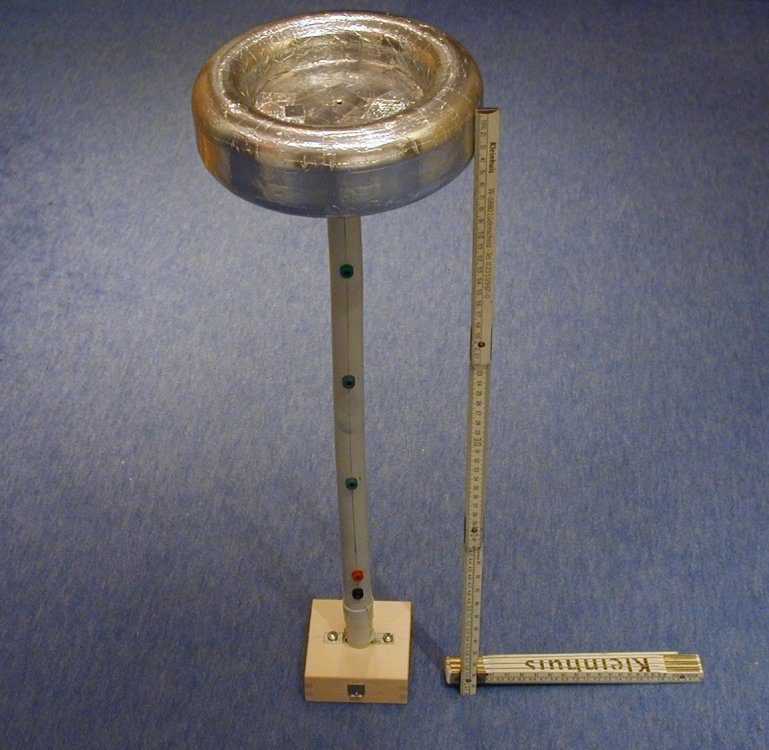
![]() I plan to
add a digital panel meter into the base for direct reading in kV.
I plan to
add a digital panel meter into the base for direct reading in kV.
40kVDC voltage probe (resistive devider, 1GOhm):
Some years later I found a commercial 40kV-probe on a Hamfest. It is a Keithley
model 1600 and looks like a nasty anal probe ;-)

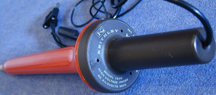

You can get a modern version of this probe here: http://www.reichelt.de/artikeldruck.html?ARTIKEL=TESTEC%20HVP%2040
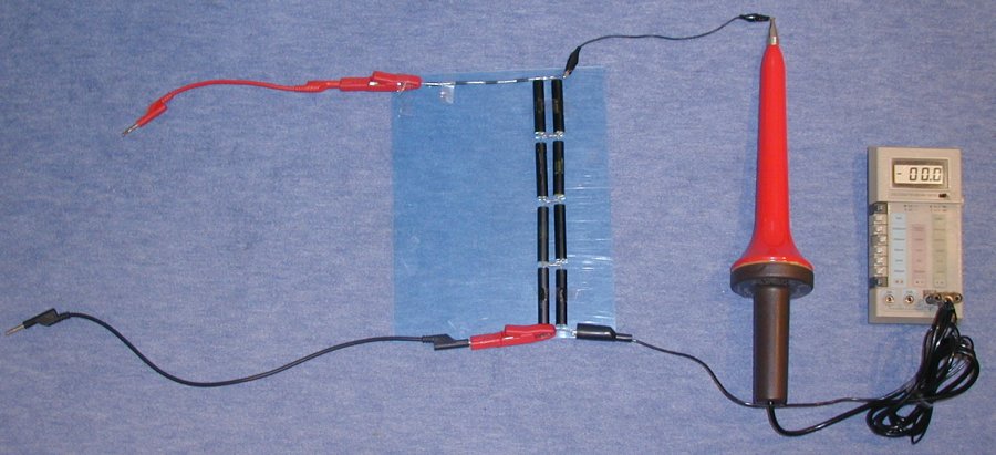
I also made a peak voltage detector from 5 diodes DD1800 and a 300MOhm resistor rated 30kV. A 1.35nF capacitor rated for 40kVpeak (8x 2.5nF, 2 strings of 4 caps in parallel, each cap rated 10kV) stabilizes the readout. The diodes are very fast (trr<150ns) so the whole thing is suited for HF.
In the following images, I used a 40kVDC voltage probe (1GOhm) instead of
the 30kV/300MOhm resistor:
Now I've build a nice housing for the capacitor and the diode as well as
a base for added mechanical stability:

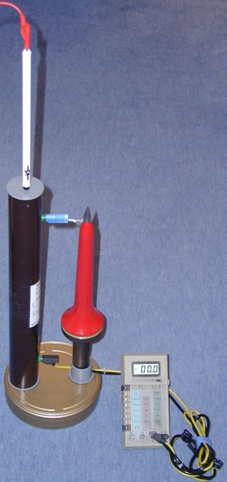
The polarity can be changed by placing the diode upside down (surprise...).
I need this feature when I want to measure HVDC with superimposed ripple
to get the peak voltage right (without the cap won't work with a digital
VOM and with the cap but without the diode the cap will present a capacitive
load which has a too big influence on the device to be characterized). The
40kV probe now looks more like a skyrocket ready for take-off.
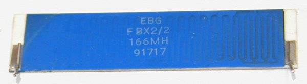
I bought some X-ray cascades from ebay with lots of 166MOhm non-inductive
HV-resistors (EBG, type FBX2/2, rated 5W at 22kV each), I'll build a nive
6GOhm/800kV-devider from them soon (36 resistors). With an additional resitor
in parallel to the VOM, the division factor will be 1:10.000.
I'll use some potential rings (like in the
Cockroft-Walton multiplier, connected to every
third resistor) and again the brown 75mm diameter tube. The resistors will
be arrangend zigzag-wise with 35mm height per element (resistor is 51mm long)
to limit the total size to approx. 1.5m:

Cross section will be like this (green is again PVC-tubing, blue the resistor,
yellow the fiberboard, brown the tube which houses the string of resistors
and grey the potential rings):

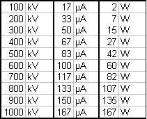
Though it has 6GOhm resistance, it will suck a lot of power when used at
it's maximum voltage rating. Since I plan to use it for my
300kV-casade, this is not such a big problem
(15W):
![]()
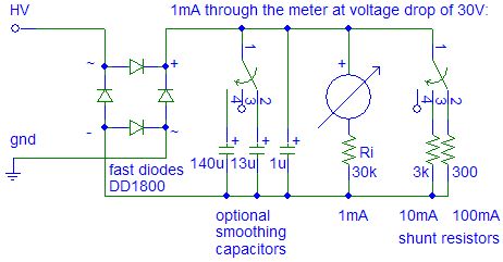
You can't measure pulsating currents well with the common digital VOM's. Therefore I buildt an analog current meter from a cheap analog voltage meter. The meter has 30VDC full scale and needs 1mA, so the inner resistance is 30kOhm. I added a rotary switch connected to two shunts. The first is 3kOhm, the seond 300Ohm. Connenting the 3kOhm shunt in parallel to the meter results in 10mA full scale, respectively 100mA full scale with the 300Ohm shunt.
Since I want to measure the short circuit current (as well as current and voltage under different loads) of some flyback drivers, I added a bridge rectifier made from four fast (trr<150ns) switching diodes (DD1800). They are rated 18kV and have a high voltage drop in forward direction (e.g. 25V at 10mA). Since this device will be used only for measuring HV-sources, the voltage drop at the meter itself (30V full scale) and at the diodes is negligible compared to the open circuit voltages of the sources (typically >3kV, up to 300kV).
When the meter is used to measure the current in a HV-line (like input current into my Cockroft-Walton-multiplier), drawing repetitive arcs makes the needle swing. This is because the input current is high when the cascade begins to recharge and low just before the next spark jumps from the top terminal to the grounded electrode. Therefore I'm going to add a capacitor right after the bridge rectifier to smooth the current (=integration over a short period of time):
Diodes are rated 20mA continious (IFAV=20mA,
IFRM=300mA, IFSM=3A), so measurements in the 100mA
setting have to be limited in time!
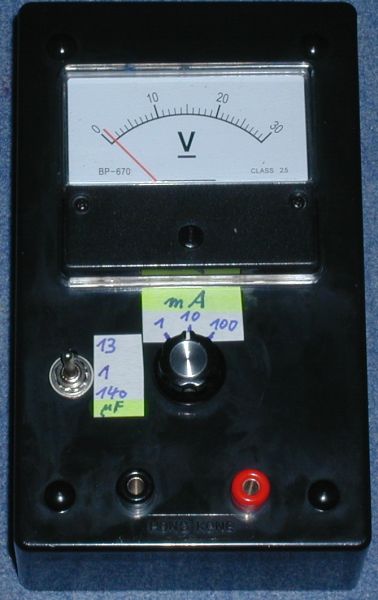
Please note that the scale still has to be changed from
30V to 1/10/100mA!
Drawing arcs from charged capacitors created high current pulses and uneven distributed voltage spikes. That puts an enormous stress not only onto the capacitor but also to the diodes, resistors and other elements in the circuit. Therefore sometimes the magic smoke comes out of them (remember: smoke is the working fluid of all power electronics - if you let the smoke out it stops working!). If a circuit element goes open circuit, it can easlily be detected by the smoke it creates once you apply the high voltage again (internal arcing). But if the element creates a short inside, it's difficult. Therefore you have to measure all the elements if something is not working properly anymore. Applying high voltage again to see the smoke is not practical since more circuit elements could die due to overstress in the malfunctioning circuit. So the best solution is to test all elements with a good VOM. Most of them also include a diode tester now. But using it for testing high voltage diodes, it will tell you all of them are dead. Why? Well, high voltage diodes usually are a series combination of many standard (silicon) diodes. Therefore the forward voltage drop is much higher, e.g. 25V at 10mA for the DD1800. That's to high for a VOM which is powered from a 9V battery usually.
So we have to apply a significant higher voltage and limit the current to a value the diode will survive.
Going trough all the diodes I currently have, the one with the lowest current capability is the KYX28/15 which is rated 2mA (forward voltage drop at 1mA is 28V). So let's make the current 1mA.
The diode with the highest forward voltage drop is my Tesla KYY29/155 which has a voltage drop of 250V at 100mA (for sure much less at 1mA). To be on the safe side (voltage wise), I'll use rectified mains voltage (230V*SQR(2)=325V. To limit the curent, I'll place two 230V/9V-xfmrs back-to-back to form an isolation xfmr. Output voltage is rectified with a bridge rectifier (plus >50nF smoothing cap for tau>0.1s) and the current limited with a resistor.
The current output is only 1mA but might lead to unexpected movements if
touched (remember, voltage is >300V). Therefore clip leads are a must,
as well as a pushbutton for activation:

Depending on the voltage drop over the diode, the needle of the 1mA-meter should move more or less. Even with voltage drop of 250V, there would be 75V left across the 330k-resistor, resulting in a current flow of 0.23mA. Reversing the diode should result in "zero" current flow (approx. 1-10uA, thats not visible on the 1mA-meter). Putting a voltage meter (e.g. a digital VOM) across the diode will give the forward voltage at the current indicated by the 1mA-meter.
Be careful when measuring HV-diodes in-circuit! You have to discharge all the capaciors in the circuit BEFORE and AFTER testing EACH diode! Else you'll be zapped for sure...
![]() This circuit
is only planned, not verified by experiment up to now!
This circuit
is only planned, not verified by experiment up to now!
I got this W-meter from an old power station which was dismantled:
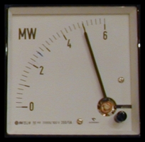

Instead of the voltage transformers (instrument transformers) you can also use resisors to supply the 100V fo full scale to the meter. The current transformers are only needed if you'll go above 5A.
This W-meter has two two switching contacts:
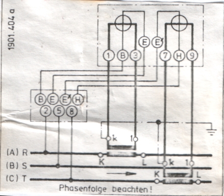
It is for 3-Phases 380V and 5A.
![]() Problem here
is that I don't have the resistors needed and I don't know the needed values
:'-(
Problem here
is that I don't have the resistors needed and I don't know the needed values
:'-(
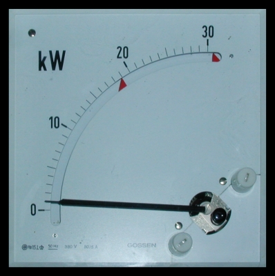
From the same old power station I got this VAR-meter:


It displays only the reactive power (not the apparent power and not the real power)! Since the needle can swing in both directions, it is a good way to tell if you have to add or remove capacitors for perfect compensation.
measures the average BPS (fiberoptic with counter and RC to voltmeter)
![]()

![]()
![]()