Exploding wires, can crushers, coin shrinkers, ball lightning
High energy page
![]()
Exploding wires, can crushers, coin shrinkers, ball lightning
WARNING: big caps (>50J) are absolutely
deadly!
Defibrillators have approx. 500J, we are dealing
with energies an order of two magnitudes higher (up to 50kJ)
here!
50kJ equals dropping a VW Golf (a german car with 1400kg) from 3.5m, better
not to stand under the weight!
![]()
![]()
|
||||||||
The Coin Shrinker (MP-Caps):
For the coin shrinker I'll use some pulse caps. I'll arrange them in modules of 10kVDC rated voltage. They usually will be charged to only 80% of their voltage rating for lifetime reasons (15th power law: charging to only 80% of maximum rating will increase lifetime by factor 28 (see my Blue Thunder page for details on derating). Unfortunately, most of the caps will die from overcurrent, not overvoltage). Since I recently acquired some 25kV caps, I'll be able to combine them with two 10kV-modules at a charging voltage of 16kV if I ever feel that 8kV is not enough for any reason.
Up to now, I have the following pulse caps:
| A1 | 18 caps |
40µF @ 2.5kVDC cylindrical |
MP-caps from Bosch (single bushing, housing is live, too) |
5 modules of 4 caps in series => 5x 10µF@10kV |
2kV across each cap | 1.6kJ | 50µF | o=10.5cm H=17cm |
| A2 | 2 caps | 40µF @ 2.5kVDC cylindrical |
MP-caps from Siemens (single bushing, housing is live, too) |
will be used with row "A1" | - | - | o=7.5cm H=24cm incl. central bottom screw |
|
| A3 | (1 cap) | 40µF @ 2.5kVDC cylindrical |
MP-cap from ITT (single bushing, housing is live, too) |
replacement cap for row "A1" or "A2" | --- | --- | o=10.5cm H=17.5cm |
|
| 4 caps | 60µF @ 2.5kVDC cylindrical |
MP-caps from Bosch (single bushing, housing is live, too) |
1 module of 4 caps in series => 1x 15µF@10kV |
0.6kJ | 15µF | o=10.5cm H=19cm incl. central bottom screw |
||
| B | 12 caps | 10µF @ 3750VDC cylindrical |
MP-caps from Bosch (9x single bushing, housing is live, too. 3x double bushing) |
4 modules of 3 caps in series => 4x 3.3µF@8(11.25)kV |
2.83kV across each cap | 0.42kJ | 13µF | o=10.5cm H=20cm incl. 11cm x 11cm bottom plate (double bushing?) |
| 1 cap | 10µF @ 3750VDC cylindrical |
MP-caps from Bosch (double bushing) |
--- | --- | --- | |||
| C | 4 caps | 250µF @ 2.5kVDC rectangular |
Aerovox YD252EW250R24A pulse discharge cap |
one module of 4 caps in series => 62.5µF@8(10)kV |
2kV across each cap | 2kJ | 62.5µF | T=10cm B=12cm H=26.5cm |
| D | 3 caps (+1 cap spare) |
80µF @ 3kVDC cylindrical |
red Maxwell pulse caps (type 34160) | 1 module of 3 caps in series (1 cap for spare) => 27µF@8(9)kV |
2.7kV across each cap | 0.85kJ | 27µF | o=18cm H=14cm (incl. top screw) |
| D' | 1 cap spare |
80µF @ 3kVDC cylindrical |
SIEMENS B25352-S3806-A009 (just like the red Maxwells above) | o=17.5cm H=14.5cm (16.5cm incl. top screw) |
||||
| E | 2 caps | 32µF @ 5(6)kVDC rectangular |
still need two more for 16kV | perhaps to be combined with row G for 16kV | 4kV across each cap | 0.51kJ | 16µF | T=12.5cm B=15.5cm H=22.5cm
T=8.5cm |
| E' | 1 cap | 28µF @ 5kVDC rectangular |
CSI 5F653TN | perhaps to be combined with row E | T=10cm B=12cm H=27(29)cm |
|||
| F | 1 cap | 20µF @ 2.5kVDC cylindrical |
MP-cap from Bosch (two bushings) |
--- | --- | o=10.5cm H=18cm |
||
| G | 2 caps | 32µF @ 3.75kVDC cylindrical |
MP-caps from ITT (two bushings) still need the third one for 8kV |
perhaps to be combined with row E for 16kV | 0.34kJ | 16µF | o=12cm H=25.5cm |
|
| H | 3 caps (+1 cap) |
6µF @ 3.2kVDC cylindrical |
MP-caps from Bosch (two bushings) |
1 module of 3 caps in series => 2µF@8(10)kV |
0.06kJ | 2µF | o=10.5cm H=19cm |
|
| I | 2 caps | 15µF @ 10kVDC rectangular |
2 caps in parallel => 2x 15µF@8(10)kV |
0.96kJ | 30µF | |||
| J | 10 caps (+1 cap) | 4µF @ 6kVDC cylindrical |
MP-caps (?, probably plastic film!) from Siemens, single bushing | 5 modules of 2 caps in series => 5x 2µF@8(12)kV |
4kV across each cap | 0.32kJ | 10µF | o=10cm H=22cm plus central screw (L=15mm) |
| K | 10 caps (+4 caps) | 100µF @ 1kVDC cylindrical |
MP-caps from Bosch (two bushings) |
1 module of 10caps in series => 10µF@8(10)kV |
0.8kV across each cap | 0.32kJ | 10µF | |
| 1 cap spare
+4 caps |
10µF @ 5kVDC cylindrical |
MP-cap from Bosch (single bushing) |
2 module of 2 caps in series => 10µF@8(10)kV |
20µF | o=10.5cm H=21cm |
|||
| 75 (+1defective +4spare) | 80µF @ 2kVDC |
red Maxwell pulse caps (type 34152), evtl. for long time charged, ok for higher voltage in short time use (evtl. tested at 120% voltage) | 15 modules of 5 caps in series => 15x 16µF@10kV |
2kV across each cap | 7.7kJ | 240µF | approx. 3.2kg each | |
| sum of 10kV-modules above | 15.4kJ | 480.5µF @ 8kV |
||||||
| L | 4 caps | 1.4µF @ 25kVDC rectangular |
General Electric | 0.72kJ | 5.6µF | |||
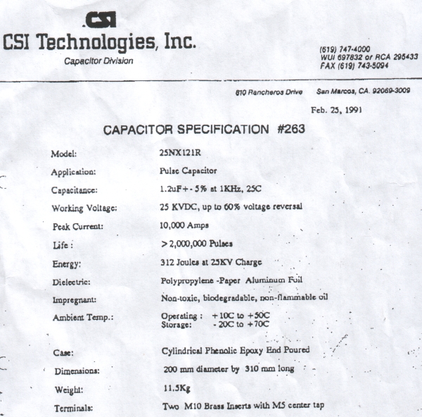
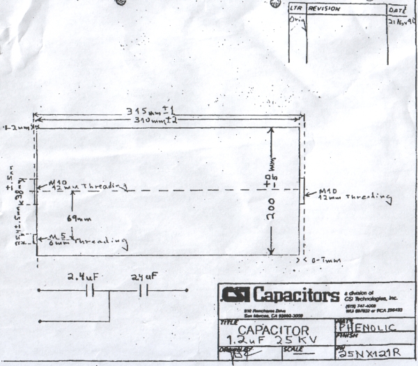
| M | 1 cap | 1µF @ 25kVDC cylindrical |
CSI, pulse rated for 2 million shots up to 60% voltage reversal! |
this cap will be the one nearest to the experiment (exploding wire or various coils) to deliver the fast current | 0.13kJ | 1µF | ||
| N | 3 caps | 1µF @ 20kVDC cylindrical |
Atesys | this cap will be the one nearest to the experiment (exploding wire or various coils) to deliver the fast current | 0.38kJ | 3µF | o=20cm L=34cm incl. screws |
|
| sum of 20(25)kV-caps above: | 0.2kJ 1.22kJ (1.3kJ) |
9.6µF @ 8kV 9.6µF @ 16kV (9.6µF @ 20kV) |
||||||
| total @ 16kV (some caps will not fit into this arrangement!) |
7.3kJ | 57µF @ 16kV |
| One possible arrangement for 8kV will be:
All the 10kV-modules listed above in parallel @ 8kV for a sum of
480µF @ 8kV = 15.4kJ. |
| One possible arrangement for 16kV will be: w/o
red Maxwells
Row A (50µF @ 10kV) in parallel with row B (10µF @
10kV) for 60µF @ 10kV, this connected in series to row C
(62.5µF @ 10kV) for a total of 30.6µF @ 16kV =
3.9kJ. |
Rectangular Aerovox caps: The Aerovox caps are an older technology that is constructed from metalized kraft paper, foil and polypropylene. (Bert Hickman got the specs from Aerovox some years back for some 25uF @ 2500volt caps YD252EW025D21A. Aerovox indicated that the maximum surge current spec for these was 1,000 amps. Hopefully mine are rated for significantly higher peak current.)
Cylindrical red Maxwell caps: Here is the data I got from Maxwell about their pulse capacitors #34160 (red cylindrical housing, one has the serial number 72722): They do not have a complete specification for this 1976-vintage capacitor in their files today. The following data was given from their database and a test report they found on file:
CSI pulse cap data sheet:
I have no idea about the ESL and ESR of all the other MP caps up to now.
On the General Atomics Energy Division website (http://www.gaep.com/technical-bulletins.html) one can find a paper which describes the derating when higher voltage reversals are applied (http://www.gaep.com/tech-bulletins/voltage-reversal.pdf).
There is also a paper on safety
(http://www.gaep.com/tech-bulletins/capacitor-performance-and-safety.pdf),
where the following paragraph is taken from:
"One particularly violent failure mode that must be considered with large
capacitor banks that are designed to operate in air, as opposed to under
oil, is the ignition of a mixture of dielectric fluid and air after the capacitor
has ruptured. In this scenario, when the capacitor case ruptures, it sprays
the dielectric fluid into the air and then the arc caused by the internal
fault ignites the mixture." So please be careful and take appropriate measures
for that case when operating your capacitor bank!
Arrangement of the caps:
The best effect will be achieved with the highest voltage (and therefore highest current) by connecting all caps in series. This is ok for the electrolytics (see section on can crusher below). But the pulse caps from Aerovox and Bosch are different types (read ESL, ESR). It's not a good idea to connect caps from different vendors in series for HV or high current applications. Differences in surge impedance may result in accidental overvolting and failure of some caps followed by cascading failure of the rest. Also, lower voltages will be easier to cope with (think of corona). As described above, I'll build some modules rated 10kV and operated at 8kV. Each module will contain only identical caps.
With a 1" diameter 10 turn #10 AWG work coil, the peak current will be in the 50-75 kA range (according to Bert Hickman). It's hard to say what the lifetime of the caps will be since this will really be pushing them...
Charging circuit:
6kV neon sign transformer (rated 80mA, will be boosted to approx. 200mA) with bridge rectifier (2 stacked 6kV@100mA - diodes each leg) for 8kV charging voltage, small variac to adjust voltage.
Releasing the energy:
A) Firing the bank of MP-caps will be done via my EG&G GP-41B-25 triggered spark gap. It usually should be operated between 12kV and 36kV, can cope with a charge of up to 0.5 coulomb and peak currents of up to 50kA. Triggering will be achieved by a simple ignition coil and light dimmer circuit via two 0.5nF/30kV capacitors like Ross Overstreet suggested on his website.
B) Should the EG&G gap ever die, I can build a robust gap out of two 60mm spheres (approx 7.5mm for 25kV according to the table in he HV-book of Jim Lux). The gap setting can be tested (VOM with HV-probe) with a small capacitance and big charging resistor.
C) NEW: On the teslamania-website of Bert
Hickman I found a nice solution of a solenoid spark gap with moving contact.
The contacts are brought close together so that the voltage is sufficient
for breakdown. But they do not make physical contact. This way, no welding
together can occure.
I intend to use such a gap here to cope with the smaller voltage and higher
energy I have now available (not so good for the EG&G gap). Perhaps I'll
use some graphite electrodes on a pneumatic cylinder driven from a
small compressor. Setup will be: compressor, switching pressure gauge (to
switch compressor off via a contactor when a certain pressure is reached),
pressure regulator (with integrated particle filter), 5/2-way valve, pneumatic
cylinder (10bar). The valve will be pneumatically activated by a 3/2-way
valve which itself is activated pnematically when the operator turns
a pneumatic switch. This pneumatic switch is actually a manually
operated 3-way-valve. It assures that the tubing vented normally so
that no accidential activation can occure. This way, the operator only has
contact to two insulating tubings with a pneumatic switch at the end, no
electric conductive wires involved.
D) Another idea is to use a pressure dependent switch (low pressure) to activate the 3/2-way valve mentioned above. In this case, the operator only has contact to an insulating tubing with a rubber bulb at the end. One squeeze and the switch will be activated.
Experiments with the bank of MP-caps:
I'll do a series of experiments with different energy levels and different number of turns and different wire diameters to find an optimum in shrinking performance. I'll start with a 10 turn coil of #10 AWG.

![]()
![]()