My 2"-System
These are the pictures of the first films I shoot from my 1997'er "small_TC". This is my second TC, but the first one that really works. I've built already a very small one (60W) as a high school project in 1986, this was one of the typical misconcepted designs with a long and skinny secondary, incredible thin wire, no chance to hit resonance frequency with the used parts etc... For a better storage of the current model, the outer dimensions are chosen that I can store the components (primary, filterboard, secondary, glass bottle caps, control cabinet etc.) in standard cardboard boxes e.g. made for xerox paper (that was a very optimistic attempt as my systems grow now more and more :^) ).
Sorry that the images are a little grainy, but I only had a very cheap camera which allows only distances over 1m, so the things of interest had to be zoomed during the scanning process. (The photos taken at the end of August'97 of my 4"-system are taken with a better camera).
|
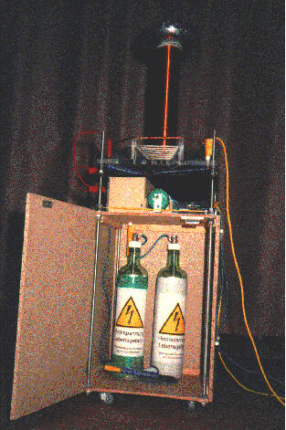
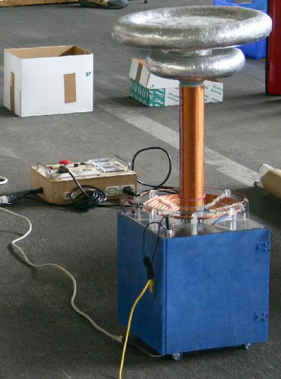
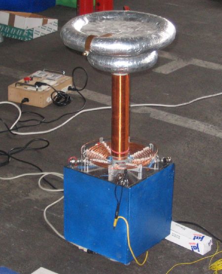
STK1TC22 | Closeup of the whole system with a different toroid (2.4"x6.6" = 6.2cmx17.2cm, 7.4pF, called T4). |
|
STK1TC23 | Closeup of the inside (where the glass bottle caps are located). |
|
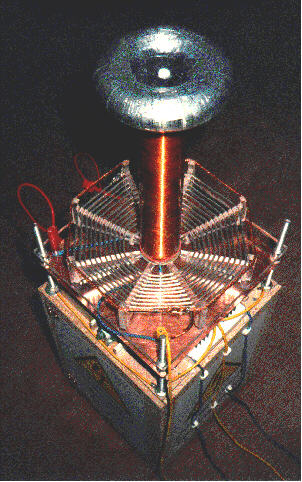
STK1TC25 | Closeup (like #22, but a little more top view). |
|
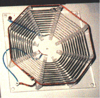
STK1TC26 | Primary (AWG12 braided halogen litz wire) with open strike protection ring. |
|
STK1TC28 | Filter board with: 2*250 turns on iron powder core (6mH) + 4*77 turns on ferrit core (34mH) + bypass caps (now blown & replaced by two 0.56nF glass bottle caps) + safety gap (perhaps I should have set these gaps not so wide with the old bypass caps) + 2 resistors 7500Ohms@3W (now blown as I switched to neons with much more current) + main spark gap (8 heavy steel rings on a wooden rod). I don't recommend the use of chokes any longer, please have a look down the page where I describe the current status of this project to see how an RCR-network will work instead of the chokes! |
 |
STK1TC29 | 5A control board (analog meters for U and I, main switch, key switch, pushbutton, fuse, various indicator lamps, sockets for ballast, HV-xfmr and two auto xfmrs with different ratios or one variac). |
sorry, to bad |
ditto |
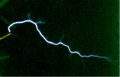
3.15"(8cm) streamer in air and "power" strike to wire (great event, but awful photos). |
|
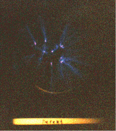
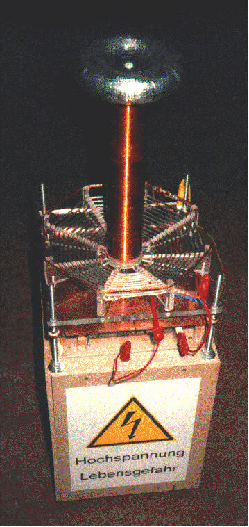
STK1TC35 | Plasmaglobe: BIG (2000W) light bulb lying on top of toroid with damaged fluorescent lamp in front of it (both ends at ground potential). Photo taken at 180W input power. |
| Right after making the first photos, I found additional identical 5kV-xfmrs at the same second hand electronic shop (surprisingly, because the two old ones are 10 years old and I never saw one of this type again!) and bought 6 more (about 6$ one). But though I used additional caps (up to 7 nF) and various bigger toroids, I was not able to generate sparks longer than 4.7" (12cm) (I tried it not hard enough...). I decided to try it with 9nF or 10nF again sometimes. |
| As I want to make things always better as they are today, I decided to make a flat version of the RQ-gap for better performance of my TC. I used 10 sections of 0.9" (22mm) dia copper, 4" (10cm) long, which gives me 9 gaps. The spacing was around 0.028" (0.7mm) as was suggested by Richard Quick in the old archive files at funet. By replacing my old gap against this one (June 15th, 1997), I achieved 8.7" (22cm) instead of 4.7" (12cm) arcs. The only thing I wonder is that my 10kV-xfmr is only capable to use 4 (max 5) of the gaps (RQ: 1.4kV/gap => 7gaps ???). After widening the old gap and trying it again, I found that the sparks were more spindly and shorter than with the RQ-gap, independent of the number of gaps (until no spark occurs due to a too wide setting). I think this is due to a better quenching of the RQ-gap. |
| As the experience grows, also the toroids did and now I'm the owner of MANY handmade toroids with different sizes. As I said, the space in my basement was very limited this time. My old basement was extremely small and allowed only one foot of sparks with an 8"-toroid (total available space between the shelves was 31" :-( ). To overcome these restrictions and have some fun in my own basement, I made a conical section out of an old sheet of plastic laying around for years in my basement. The height is 11.8"(30cm), bottom dia 7.9"(20cm), top dia 4"(10cm). I taped it with aluminium tape as I did it with the toroids. The thing was placed between two toroids on top of my coil. This allowed me to arrange my top capacitance more vertical to get longer arcs without going to a toroid with a larger diameter. Current record set on June 18th. 1997 with 540W input power is 14.4"(36.5cm) arcs (point to point). On June 20th. 1997, I performed a test with one of my 63mA@8kV-neons and achieved 17.3" (44cm) with 635W input power. The primary capacitance was about 10nF in this case. I think the spark length can be increased furthermore by the use of a bigger primary capacitor of up to 18nF (and of course a better one than the salt water caps of now). |
Some of the photos taken in June'97:
|
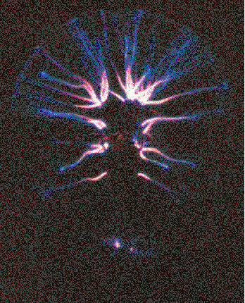
Beautiful display of an 20cm plasmaglobe (about 300VA input power). | |
|
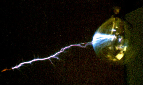
Arc from the discharge electrode to an 12cm plasmaglobe with grounded filament (about 540W input power). | |
|
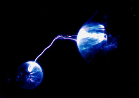
Arc between an 6cm and an 12cm plasmaglobe, filament connected to the toroids resp. grounded (about 540W input power). | |
|
Streamer from the discharge electrode. |
| The braided halogen litz wire of the primary is now replaced by a bunch of 7 twisted solid copper wires, each 1.8mm (AWG13). The main system spark gap is replaced by a small modified RQ-gap, consisting of 7 pieces of 22mm dia copper tube (2" long) lying next to each other in a distance of 0.5mm. The HV-xfmr is now located inside of the housing at the bottom. Above it (yes, that will be a bad situation if one bottle will rupture...), there are the salt water caps (9 small mineral water bottles). The capacitance of them is much to small (only 5.7nF instead of 18nF), so they will be replaced in the future by plastic caps (click here to go to my capacitor page). With the new primary I think I have around 14µH and a frequency of around 550kHz with the conical section electrode on top of the toroid. The current in the primary coil seems to be around 200A assuming a breakdown voltage of 10kV in my gap. |
| After a long search, I found some ceramic disk type capacitors 1nF@10kV. Assuming this as the DC rating, I put 6 of them in series and replaced the old bulky saltwater bypasscaps of my 2"-system (currently driven by 9.5kV@540W) with them. For safety reasons, I decided to add bleeding resistors over each cap. I took four 1MOhm@600V-resistors per cap for a total of 24MOhm@9.5kV. The discharge time constant is 4ms, bleeding current 0.4mA and reactive current in the ceramic bypass caps about 0.5mA at line frequency. So the losses in the filter board are about 2% of the input power. I don't recommend the use of chokes any longer. Instead, I'll use an RCR-network and perhaps some MOVs to filter the R coming backwards form the coil. |
Update February '99 - October '00, reworked in March 2002, Update October2004:
| The ERO caps (MKP = selfhealing aluminized PP, 62nF, 1kVDC, 330VAC, 1500V/us
in series/parallel combination) that I use in Vitamini
still perform very well. I aquired some more of these caps and plan to use
them here in the 2"-system to reduce its size (height) and improve the
performance. I expect at least 50cm sparks (2 times the winding
length) with 540W input power and I'm even dreaming of getting up to
75cm (3 times the winding length). John Freau's formula spark length = 5.8 * sqrt (power input) / 4th root ( BPS) predicts 108cm, but this is for more common systems, I'm sure I'll get not as much because my secondary diameter is far to small and I use not enough inductance in the primary circuit.
Due to the good lifetime of these (ERO KP1836, 1000Vdc, 62nF) and other caps,
I decided to go for only 15 caps per string. I will use about 120%
(160%) of resocap size, so I will make
2 layers of up to 4x 15 caps each. Resocap size is approx. 18nF, so the optimum
120%-LTR value will be around 22nF.
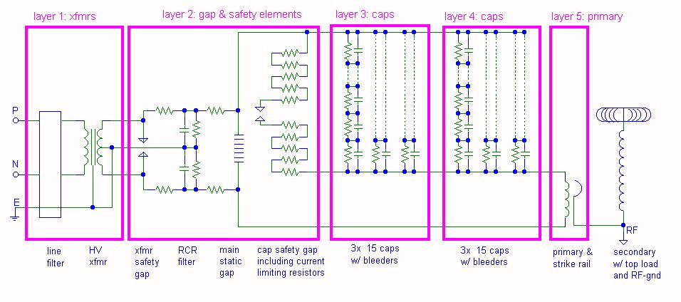
Compared to the old sw-caps, I will be able to reduce the total hight of the 2"-system by about 16cm when using the new plastic caps (and additional 4.5cm by rearranging the filter board and static gap). Wiring scheme:
A gap (~2mm wide) between the individual rows of caps has the advantage that you can inspect the sidewalls of the caps in case some of them blew. Height of the caps is approx. 2.7cm, I arranged them in two layers. I use an 1.8MegOhm bleeding resistor across each cap. For increased cap lifetime, I added about 14Ohms in series to the safety gap (8x 1.8 Ohm) for reducing the voltage risetime stress (=current) on the caps in case of saftey gap firing down to a value near standard TC operation.
First test with the new MMC was done on 08.07.2005: Energy per bang will be approx. 1.92J (compare this with the 0.52J of the latest sw-cap arrangement with 9x 0.63nF or the 1.92J with which I achieved 1.5m arcs using my 4"-TC with sw-caps in 1997!), peak current in the primary around 670A (I have to recalculate this for the new toroid I'll use).
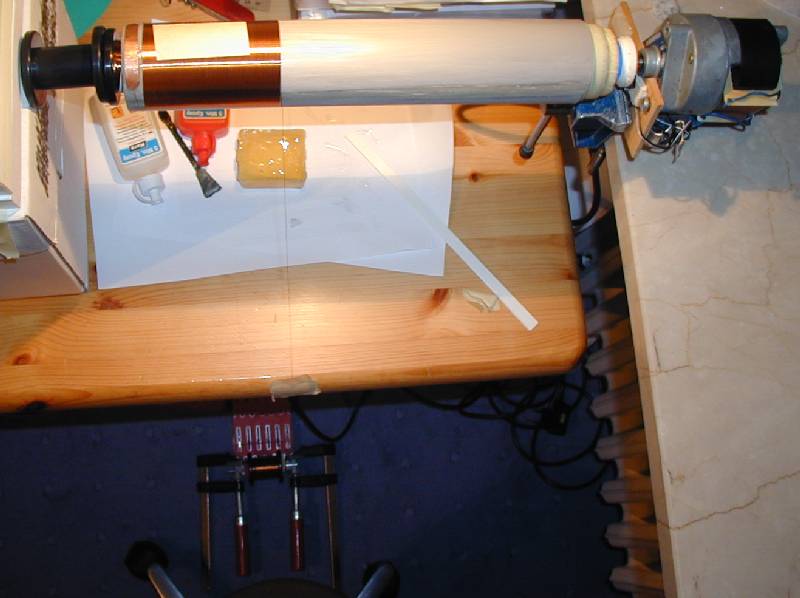
New secondary:
Results so far (20.07.05):
|
![]()
![]()

