
This web page describes the behaviour of resonating coils and transmission lines. I'll try to show that these behave in the same way and will explain the meaning of terms like 1/4 wave and so on. I will also explain how terms like series resonance and parallel resonance apply to these systems.
For ease of explanation I will stick to loss-free resonators with two ports.
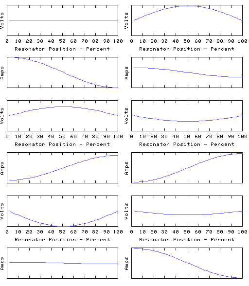
Consider the following three animations:
 |
 |
 |
|
|
|
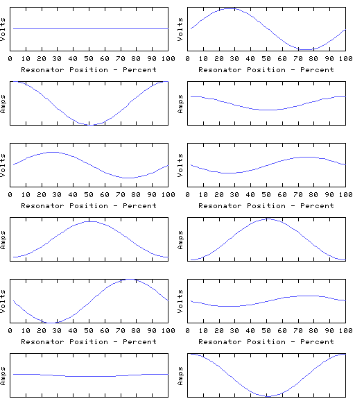
These are distinct resonant modes of the same resonator. The graphs show voltages and currents along an electrical resonator such as a coil or transmission line, but they are typical of most resonating structures, and can be demonstrated with a piece of rope pulled tight and waggled up and down. They are often called standing waves for obvious reasons. The frequency of each oscillation should be different, but I've made them all the same in the animations.
Each resonance is characterised by a number of points along its length where the voltage is zero all the time, along with other points where the current is always zero. In between these the amplitude (voltage or current) varies smoothly to a 'maximum', and then down again to the next 'zero', with a shape roughly sinusoidal but with the precise detail dependent on how the reactance is distributed about the resonator.
The distance between a zero and an adjacent maximum is described as a 1/4 wave because a travelling wave moving along the resonator would take 1/4 of a cycle to get from one of the zeros to the next maximum. Therefore the first animation is labelled 1/2 wave because there are a total of two 1/4 waves spanning the length of the resonator. The other animations are a whole wave, and a 3/2 wave, etc.
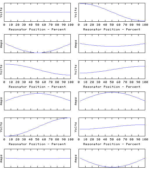
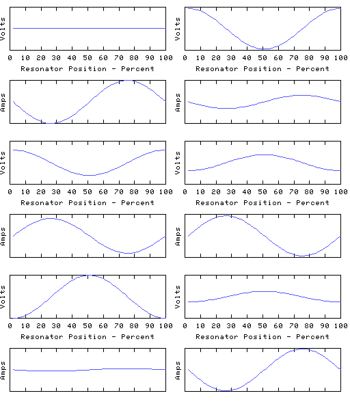
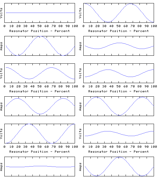
The coil modelled above has both ends grounded. This means that the voltage at each end is clamped to zero, but the end currents are free to do what they want. We can instead leave both ends open to obtain a different resonator with a whole new set of resonant modes:
 |
 |
 |
|
|
|
We now have the end currents clamped to zero, leaving the end voltages free to do what they want. The first mode is still a 1/2 wave, the second a whole wave, and so on, but all the voltage zeros have turned into voltage maximas, and vica versa, and like- wise for the currents too. Even though it may be the same coil involved, the change to the terminations turns it into a completely different resonator, and the resonant frequencies of the 'open-ended' coil may be quite different to those of the same coil with closed ends.
Therefore, when talking about a resonant mode of a coil, we must not only say how many 1/4 waves span the resonator, we must also specify what terminations are being applied. In the first set of graphs the resonator presents a low impedance at the ends, in the second set a high impedance.
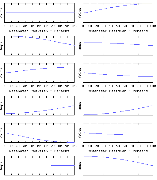
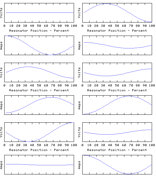
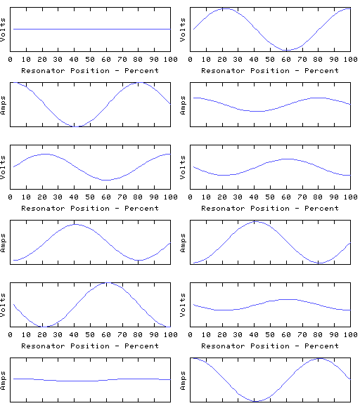
As another example, we can ground the left hand end of the coil and leave the other end open, to obtain yet another resonator, having resonant modes such as:
 |
 |
 |
|
|
|
This time we have an odd number of 1/4 waves in each mode, unlike the first two resonators which both had even numbers.
Note that however we terminate the resonator, it has a lowest frequency resonance - the fundamental - which has either one or two quarter waves to it, depending on the applied termination.
The asymmetry present in this arrangement offers a convenient way to transform AC power from a low to a high impedance, and vica versa. For example the left hand end of the coil would be connected to a low impedance driver which is arranged to feed power into the coil at the frequency of one of the odd 1/4 wave modes, and the right hand end can then offer the power efficiently to a high impedance load. This can be called 'reflection' or 'transformation' of impedance and is a very common use for electrical resonators. For example a resonator may be used to convert the low (circa 1 ohm) output impedance of a solid state transmitter to, say, the 75 ohm impedance of a dipole antenna.
The necessary values of resonator reactances can be calculated from the required input and output impedances. For many applications in radio engineering, the distributed self capacitance of the coil is insufficient to meet the required C and extra capacitance is added, usually at one end or the other of the coil (but sometimes it is hung on to the coil at various taps along the way). Under these conditions (self-C much less than end-connected C) the coil current is almost the same at each end and the circuit closely approximates the idealised lumped circuit model involving L and C elements - each of which is either purely L or purely C.
It is important to appreciate that the view of the resonator in terms of 1/4 wave segments remains valid. All we've done is to shift most of the overall capacitive reactance to the ends of the coil.
This 'approximately lumped' arrangement still exhibits a spectrum of resonant modes, and continues to offer the same type of impedance transformations, with L and C being calculated from the required impedances in the same way. No change in the essential physical principles occurs when we move from the tuned transmission lines of the UHF transmitter output stage to the wound coils and capacitors of the LF transmitter, or indeed to the Tesla coil.
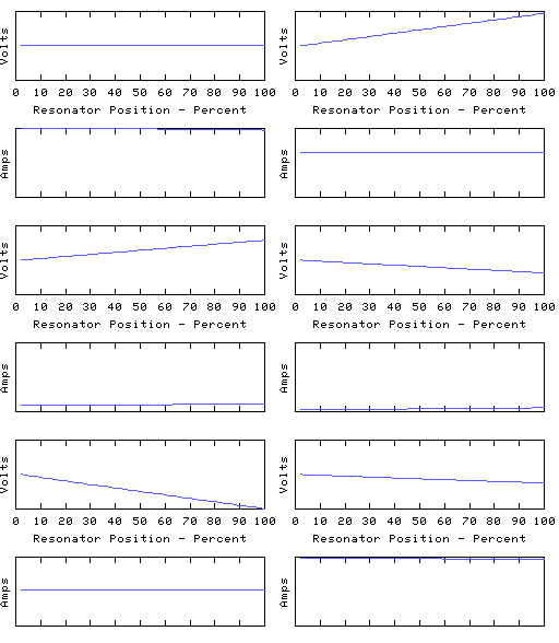
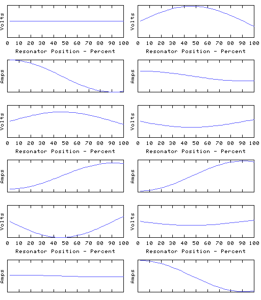
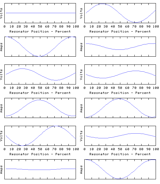
To drive the point home, here are some animations of a coil in which most of the capacitive reactance is applied at the right hand end:
 |
 |
 |
|
|
|
The left hand end is grounded and the right hand end is open circuit (all the coil current is disappearing down the end capacitor). In the fundamental mode, the coil current is almost uniform, and the coil voltage distribution is determined largely by the distribution of self inductance of the coil. In the higher modes, the right-hand quarter wave of the resonator appears severely truncated - it is still a whole quarter wave but much of the electrical length is supplied by the end capacitance.
This rather 'lumped' looking resonator still has a spectrum of resonant modes, because the coil still retains some distributed capacitance - this is always the case with any real coil! If we could make the coil self-C go to zero and thus move to the idealised lumped circuit theory model, all the resonant modes except for the lowest will rise to infinite frequency, leaving us with a single resonant mode - the fundamental. This used to have the distinction of being the lowest frequency mode - it is now the only remaining resonant mode in this circuit theory idealisation of a resonator. However, the 1/4 wave or 1/2 wave character remains intact and (since the fundamental resonance must be one or other of these) the choice between the two is set by the termination conditions.
Thus, whether an idealised LC circuit is treated as 1/4 wave or 1/2 wave depends on how we connect to it. That brings up the subject of series and parallel resonance.
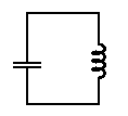
A coil connected to a capacitor is just a resonator. It makes no sense to describe it as series or parallel resonance. That distinction only arises when we open up a port into the resonator in order to connect to it. If a port is created as follows,
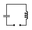
a source looking into the terminals will see a low impedance as it passes through the sole resonance of this idealised circuit, and we say the source sees a 'series resonance'.
On the other hand, the port
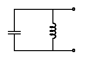
offers a high impedance to a source at resonance and this is described as a 'parallel resonance'.
The resonance is the same in each case (ie resonator voltages and currents are the same), it is just that the two different ports give two quite different views of it. With the 'series' port, anything attached to the terminals experiences the full circulating current of the resonator. With the 'parallel' port, a connected device sees the full resonator voltage.
In some cases you may not be too sure whether you have a parallel or a series port. To resolve the issue for a particular circuit, imagine placing a variable resistor across the terminals. This will absorb energy from the resonator and reduce the Q factor. Now in which direction do you vary that resistor in order to reduce the loading and therefore increase the Q factor? With the series port, reducing the resistance towards zero reduces the loading. With the parallel port, increasing the resistance towards infinity reduces the load.
Now if we introduce two ports, we can have one of the following permutations:
|
a) one port in series, the other in parallel, eg:
|
b) both ports in series, eg:
|
c) both ports in parallel, eg:
|
There are numerous variations on these themes, eg tapping into the coils and capacitors, but they can be classified roughly into one of the above types. Now the important things to note are:
1) In cases like (a) where one port is series and the other parallel, the ports are at opposite ends of a 1/4 wave resonator and the circuit offers the impedance inversion which comes from that.
2) If both ports are series (b) or both ports are parallel (c), the ports are separated by either zero or one 1/2 wave resonances. In this case there is no impedance inversion - meaning, if the output load resistance is increased, so too is the input impedance to the network. Case (b) can be seen as a 1/2 wave with the two series ports shorting the ends. In case (c) the two parallel ports are joined and shunted by a quarter wave line with the far end shorted. In this example the ports are separated by zero half-waves. Later I'll describe a different example of case (c) involving the pi network.
When we say 'grounded' or 'shorted' and 'open' here, we can take these to mean that the terminating impedances applied to the ports are (respectively), rather less than or rather more than, the characteristic impedance sqrt(L/C) of the resonator.
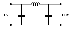
Now both 'In' and 'Out' are tapped across the C the resonator, so they are both parallel ports into the resonator. Therefore we expect 1/2 wave behaviour. We can split the resonator into two 1/4 wave sections by cutting into the coil...

C1+L1 form the first 1/4 wave section, transforming the hi-Z at the input to a very low Z. The second 1/4 wave section of L2+C2 transforms back to a high Z again. Thus when looking at a pi network, you would expect to see a voltage 'zero' near the center of the coil, and the voltages at in/out would be opposite in phase - a typical 1/2 wave resonator. The resulting voltage and current distribution along the pi-network coil would be something like:
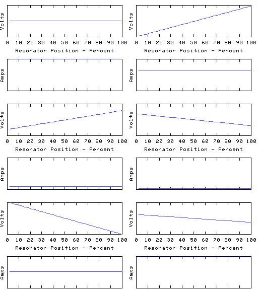 Because each of the two 1/4 waves of this mode are dominated by the
two end capacitances, the voltage profile is virtually linear and
the current is almost uniform. Remember - the same is not true of
the higher modes - only the end 1/4 wave segments are modified by
the end capacitance.
Although this is very much a 'lumped' resonator, it clearly demonstrates
all the properties we expect of a 1/2 wave resonator. In moving from
this lumped-looking circuit to a resonator in which all of the capacitance
was distributed, eg a coaxial line, no new zeros or maxima are introduced,
and the voltages and currents maintain all the same phase relationships. The
only difference to show up is the detailed shape of the voltage and current
curves - the voltage becomes more 'S' shaped and the current more bow shaped.
For this reason, electricians often come to believe that there is some basic distinction between, say, resonators made from wound coils and those made from transmission lines. They will often regard circuit theory approximations as the reality and deny the underlying physics which shows that there is one common set of behaviour regardless of the amount of end loading.
Remember that only the lowest resonant mode is substantially effected by reactances applied at the ends. The frequency of this mode is lowered, often quite considerably and as a result the higher resonances can often be disregarded. But sometimes it pays to remember that the other modes still remain - especially if some active device in the circuit happens to be generating energy at one of those mode frequencies.
To experience this, take any LC resonator which you consider 'lumped' and sweep it with a signal generator applied to one of its ports. The predicted LC resonance will be seen to be the lowest of a whole spectrum of resonant modes.
Voltage and current distributions of a real coil have been measured accurately by Terry Fritz, see http://www.abelian.demon.co.uk/tssp/pn2510/ and http://www.abelian.demon.co.uk/tssp/tfcp260302/.
Idealised lumped models in circuit theory can be extended to account quantitively for higher modes - by adding more pairs of L and C. Each extra LC can be arranged to account for the behaviour of one more mode.