Computer Controlled Tesla Coil Winder
10-19-97 Terry Fritz
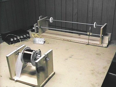
This is the computer controlled coil winder. It is made from common wood and hareware parts. None of the dimensions are critical. And only common tools are needed. A drill press is a big help but a hand drill can do the job. The wood parts should be screwed, glued, and supported very well to provide strength.
In the forground is the reel of wire.
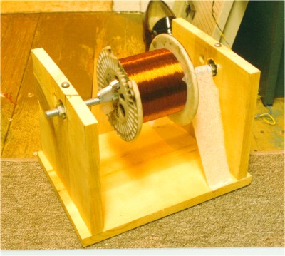
The reel is on a 1/2 inch all-thread axel shaft that is run through bearings mounted in a wood frame. Nuts are used to lock the reel in place. There is a piece of foam to the right of the reel that provides friction so that the reel will not unwind or turn without a light tug on the wire. There is electrical tape on the shaft under the foam so that the threads will not slice up the foam. The bearings have a 1/2 inch center hole and a 1 1/8 inch outer diameter. They are held in 1 1/4 inch holes drilled in the sides of the frame by 1/4 inch bolts that clamp them in place. Use at least 1/2 all-tread rod. Thinner rod is too unstable. If you want a longer winder use 3/4 inch rod. This winder uses 36 inch long rods and can wind a 30 inch long coil. You can get longer and heavier rod but you may need to have it ordered by the hardware store (look in the phone book and ask around. It is used all over for many purposes). Be sure it is straight and the threads are well formed.
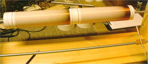
The winder itself is mounted on a long board with two upright boards at each end. There are two bearing mounted 1/2 inch all-tread shafts. One holds the coil form while the other holds a stylus that allows the wire to pass through. The coil forms are mounted to the rod by disks that are made for each diameter of form. The mailing tubes shown here came with end caps that only needed to have holes drilled. Note that I am doing two small coils at a time in this picture.
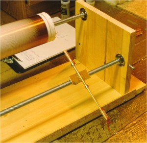
The stylus has nuts soldered to the base that connect it to the shaft. As the shaft turns the stylus moves down the winder controlling where the wire is wound. One good trick is to cover the coil form with paper and tape an ink pen to the stylus. Then you can run a test wind with the pen writing on the form. In this way you can test everything beforehand. This is very useful.
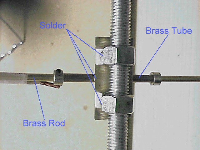
Bottom of the stylus assembly. A rod can be moved in and out for different coil form diameters. It is locked in place by small collars with set screws (hobby shop).
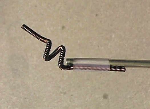
There is a coil of #22 wire that is made by twisting enamled wire around a thin rod with a hand drill. The wire is passed through this guide and it is then twisted to provide tension on the wire being wound. The wire sizes my need to be changed with different wind wire sizes.
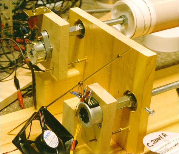
Both shafts are turned by motors. The shaft that holds the coil form is turned by a 10 RPM syncronous motor. A fan cooled the original stepper motor. the motors are mounted to wood bases that are allowed ot float in their mounting to account for slight wobble. It is difficult to drill the mountings perfectly so this mounting allows for some drilling error.
Setup with new stepper motor. The new motor is much better.
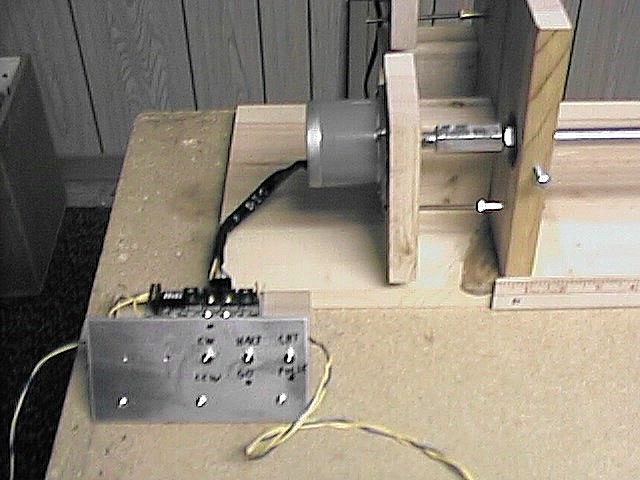
The coil form motor runs on 110AC and has a switch so that it can be turned on and off with ease. The motor is mounted on a small wood block that is kept from rotating by a small all-thread brass rod. This block is allowed to "float" which allows for imperfect drilling of the coupling nut. A coupler nut connects the motor shaft to the 1/2 inch rod and the motor is basically held up from the 1/2 inch shaft.
The stepper motor for the stylus is mounted the same way. The coupling nut has a short all thread sectoin in it that is drilled for the motor shaft and a small lock screw.
The original stepper motor grew very warm during operation and I used a fan to cool it. I have found another type of stepper motor that is much more robust and cheaper.
It dosen't overheat and is a better choice. Of course, any good large unipolar stepper can be used.
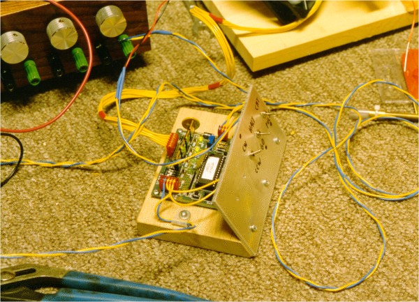
The motors are controlled by a unipolar stepper motor controller board that was purchased. This board can wind without the computer's help and has other on board features that a very handy. I added switches for starting and stoping the motor, direction, and computer or internal contorol. The board costs $80 but I would not go any other way. It is possible to interface to motor to a printer port but that would be harder than simply plugging this board in. The winder is powered by a +5 and +24 volt power supply that runs the board and provides power to the stepper motor.
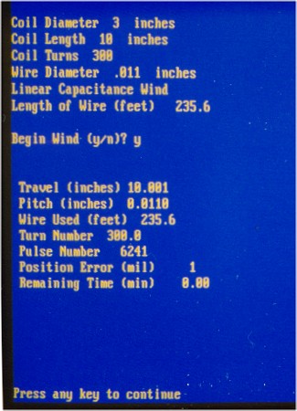
The motor controller is connected to any IBM-PC style computer through a serial port. The program is a very simple Qbasic program that runs from Qbasic which is included with MS-DOS. I use the TX pin on the interface and pulse it to pulse the motor. I have a 5000 ohm resistor in the line to protect the computer from any misshaps. Sending CHR$(240) to the port provides a nice square pulse to the controller board. There are other possiblities, but this is how I do it.
You can run this prorgam as is to see how it works. Type QBASIC at the DOS prompt and run it. Select an unused com port when it askes. The program can be easily modified to suit any situation. It should only be run from DOS when winding a coil because the WINDOWS dos prompt will mess up the programs timing. I use WINDOWS NT so I use a bootable floppy disk with this program, the system, and QBASIC on the disk. The program can be printed out with any text program. The program should be easy to convert to other systems as needed.
Here is a list of special parts: Parts.txt
Questions can be directed to: terryf@verinet.com
Any suggestions, clarifications, spelling fixes that I should add to this page are very welcome.