Info on my first apartment coil!
| Picture | Description |
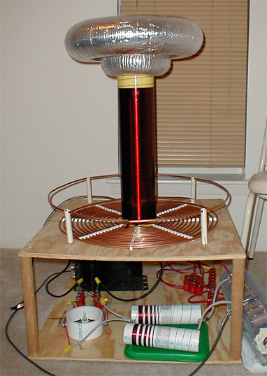
| The 900 Watt Coil | First off, let's start with some notes on this coil and it's native surroundings. Living in
an apartment on the 3rd and top floor of the building, I didn't have the much needed access to
a nice outdoor RF ground. The wall plug's ground for an RF ground was out of the question,
espescially when you run the good change of frying everybody else's stuff in the apartment
building. So, there I was, with NO Rf ground. I was content to wait and set it up back home
where there were lightning rods installed, but it just happened that the grounding tab on my
secondary ended up resting comfortably on copper tubing lead from the first turn of the primary
underneath that plywood that it all sat on. I left it there so it could leech its power from
the primary, and it works well! Just VERY dangerous.
The finished product. All part and pieces stuck together. THe NST protection circuit can be seen on the bottom left under the primary. It consisted of a 233pf cap bank and homemade choke for each HV lead, and a safety gap. The secondary was wound on dried, sanded, and sealed 4.5" PVC, ~980 turns. The toroids were all various sizes: Two 4"x15" toroids, one 3"x12" toroid, and one 3"x6" job. All are flexible aluminum ducting wrapped around aluminum burner pans and covered (badly) with aluminum tape. Pictured is one of the 4" toroids on the 3"x6" one. I didn't have any way of really adjusting the height of the secondary over the primary, so to avoid several recurring racing arcs on the secondary, I stuck on a shorted strike rail. Worked wonders! It has all been disassembled and packed away. |
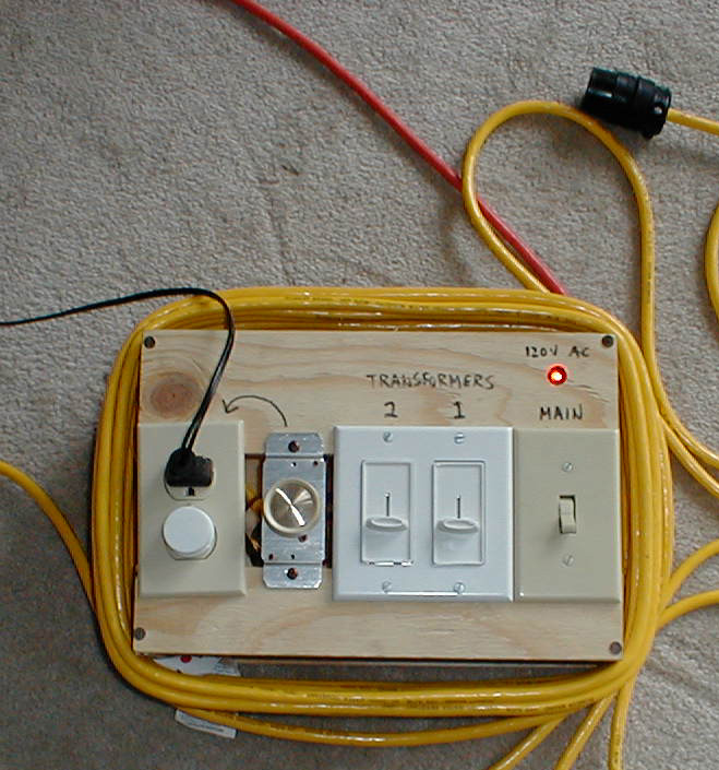
| Control Box | Here's the control box I made. I had scrap plywqood laying around, a spare on/off light switch and 600W dimmer switch. I decided to use dimmers to control the total power output of any NSTs that I might use on the coil, and bought two 1000 Watt slide dimmers with built-in RF filters. The '120V AC' neon lamp indicates a live connection to the household circuit. The light switch then powers all three dimmers when flipped 'on'. The 600W dimmer switch controls the outlets next to it and another neon lamp (in white plastic cylinder thing) lights when the outlets have power. I wanted to wire it up directly to the light switch, but I ran out of wire nuts and hadn't fixed it up as of this picture. The black plug and cable plugged into the top outlet goes to a small AC fan that blows over the spark gap. The orange cable is the 120V in, and the two yellow cables are the 120V leads from the 1000 Watt dimmers leading to any NTS that would be used. The end plug on one of the NST cables can be seen in the top right corner. |
| Allanson 15/60 NST | Input power was provided by one Allanson 15kV, 60ma neon sign transformer |
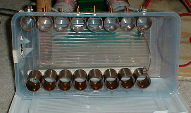
| Static Spark Gap | T he static spark gap was wired between the two HV leads and consisted of 16 copper tubing couplings, but only 8 were ever used at most. It was all bolted into a cheap Tupperware box with 8x32 brass machine bolts. |
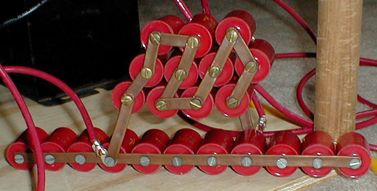
| Capacitor Bank | The capacitor bank started out as 22 30kV DC, 500pf doorknob caps wired in parallel with flattened scrap .25" copper tubing used as the bus between the caps. The entire doorknob cap bank was replaced with one PlastiCap oil-filled 80kV DC .01uf cap, and I saw an increase of 10" after tuning! The frequency of the primary also shot up considerably, as I had to tap the primary a full three turns farther in. |
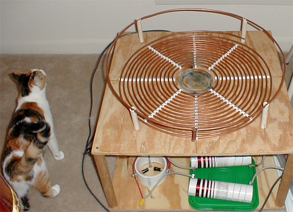
| Primary Coil | Here's the primary coil. 14 turns of .25" copper tubing tacked into 2'x2' plywood with .25" coax wall tacks. The little nails actually stuck out underneath the plywood. :P The blue in the middle is wax that was melted and dripped into the circular channel for the secondary. It was used to help level the secondary on the plywood. I think my primary was too short by two full turns, and I was actually tuning at a harmonic on the secondary. I can't remember for sure. Cleo had to investigate, of course! |
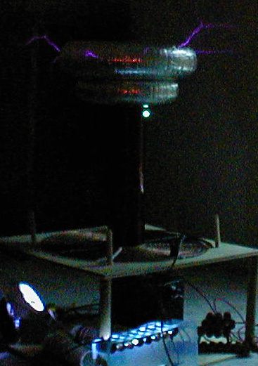
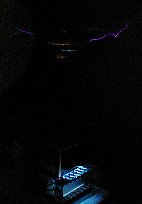
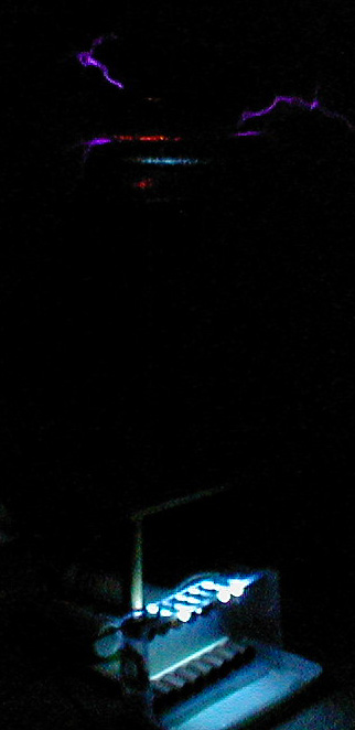
| Junk Streamers 1 Junk Streamers 2 Junk Streamers 3 Junk Streamers 4 |
Pictures of several 24"-28" streamers that just didn't turn out very well. In fact, they barely turned out at all. The first picture caught the saftefy gap is firing! Very Bright! Also, there's a rather nasty little flashover between two of the topmost windings on the right. The rest of the pictures are fairly mundane and very poor. Maximum output was 38" arcs to a spare 4"x15" toroid resting on a glass table nearby. |
| no video yet | I have several videos of the tesla coil in action, but can't seem to get anything to work when it comes to getting them on the computer. They will be posted as soon at the video capture device that I broke gets replaced. |