| Done: | |
|
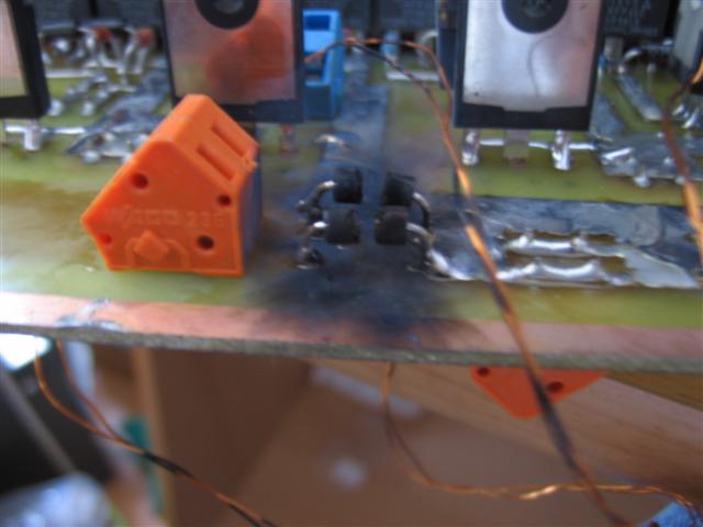
-develop circuits, PCBs,... -produce and mount PCBs -tests and calibration -test setup -test (12V, 24V, 48V, 230V) Result(12V,...,48V): no spark output, fluorescent lamps light up Result(230V): 400V supressordiodes exploded :/D Conclusion: repair circuit(done) and continue debugging... | |
| To Do: | |
|
-run simulations of the PreInterrupted mode -build case -integrate relais, fuses -integrate feedback -integrate audio-modulation |
|
|
This is the signal generation part. red: 2Vpp Sine with 2.5V offset green lines: threshold voltages for the PI-signal (variable) blue signal: 50/50 signal for the fullbridge (5V TTL) yellow-brown signal: PI signal (5V TTL) To see an animated version of the signal generation part: -->Movie (366kB/encoded with DivX6.0) |
|
| This is the functional overview. But it is NO 1:1 PLAN!!! Just to see the most important functional parts of this circuit. |