A Low-Cost, High-Performance Tesla Coil Power Supply based on Microwave Oven Transformers
By: Gregory R. Hunter, March 2000
Many Tesla coil builders, especially those on a limited budget, must seek alternatives to the neon sign transformer (NST). It is in this spirit that I decided to investigate microwave oven transformers (MOTs) as a possible power source for Tesla coil service. NSTs are still the best and most popular choice of power supply for novice Tesla coil builders. They offer many advantages, such as internal current limiting, a wide range of voltage and current levels, and effortless paralleling for increased power as the coil builder gains experience. Unfortunately, used NSTs are difficult to locate in many parts of the country. Likewise, new NSTs are prohibitively expensive for the hobbyist. In fact, locating a suitable high voltage power supply is often the single most vexing obstacle for the budding coiler. MOTs, on the other hand, are universally available for free or at very low cost from broken microwave ovens. Sometimes broken ovens may be had simply by asking for them. Likewise, in many communities broken appliances are placed at curbside for collection by city recycling & sanitation services. MOTs offer low (or no) cost, ready availability, and ample power output. However, they are not without drawbacks.
Drawbacks of the MOT for Tesla coil use include too little voltage and too much current. The most common type of MOT found in household-type 120V/60Hz ovens develops between 1900 and 2400VAC at 300 to 900ma. Power and voltage generally increase with increasing physical size. In other words, the bigger the MOT, the higher its voltage and current output is likely to be. 2KV is too low to reliably fire a spark gap, and the several hundred milliamps of current is likely to quickly overheat any spark gap narrow enough to arc at such a low potential. Another problem with MOTs is that they lack adequate internal current limiting for the near short-circuit operating condition found in the spark-excited Tesla coil. Although the MOT may seem undesirable for Tesla coil use, its disadvantages may be overcome with a little effort. Higher voltage would certainly be a good thing. The simplest way to achieve it is to use more than one MOT. Another option is to use some sort of voltage multiplying circuit.
My own MOT power supply is based on two, 120V/2400VAC transformers garnered from broken 900 Watt ovens. It is patterned after a similar power supply I read about on Finnish coiler
Marco Denicolai's web page. I also salvaged the 0.9uF/2100WVAC capacitors and the high voltage silicon rectifiers found in the same ovens. I made every effort to control cost by making maximum use of materials already on-hand. Before I built the MOT supply, I tested out the design as a crude lashup. For the testing and development stage, I first assembled the MOTs and doubler/filter components on a clear spot on my workbench. Mains power was supplied by a 240V/20A air conditioner outlet. The setup was thrown together using duct tape, hot glue, and wire nuts. It looked like hell, but it worked well enough that I decided to progress to a more permanent arrangement.I mounted the two MOTs side-by-side on a small scrap of .125" Aluminum sheet stock from my junk box using self-tapping screws. I cut the Aluminum base so that it barely fit into a standard US military .30 cal. ammo can which happened to be in my shed. I bored a 3/4" hole in the back of the can to admit the 240V power cord through a standard electrical service panel cable clamp. I bored two more holes in front to accept HV output bushings fabricated from 1/2" schedule 40 PVC pipe and caps. I wired the 120V MOT primaries in series with the 240V, and connected the mains earth lead to the MOT cores. I routed the 2400VAC from each MOT output terminal through the homebrew PVC HV bushings, giving me a very powerful 4800VAC power supply. Next came the doubler/filter assembly.
For the voltage multiplier, I chose the same simple half-wave
voltage doubler circuit employed in the microwave ovens. I used two identical voltage doublers--one on each MOT output bushing. Since the doublers develop opposite potential, the total output voltage reaches approximately 12KVDC in the form of 60Hz pulses. For RF protection, the diodes are bypassed by two .001uF/10KV ceramic disk capacitors. Additionally, the HV output is routed through a pair of 100 Ohm, 55 Watt wire-wound power resistors. These provide resistance plus a certain amount of inductance to discourage RF from flowing back into the power supply.I breadboarded the doubler/filter circuit on a scrap of 1/4" thick Plexiglas sheet cut to fit the front of the ammo can. I took this approach for two reasons. First, the outboard design keeps the electronics away from the hot transformers. Second, it allows for quick repairs in the rare event of a blown diode. All the connections are made with spade terminals for rapid removal and replacement of parts. I strapped the big doubler capacitors in place with large plastic cable ties. The diodes and their protective bypass caps are suspended by stiff wire leads. Likewise, the filter resistors are suspended from stiff, solid copper wire leads that I soldered on. The screws that secure the filter resistors to the Plexiglas also serve as the safety gaps. They pass through the Plexiglas and come within about 3/8" of the grounded steel ammo can.
As a final measure, I covered the MOTs with three quarts of non-detergent motor oil. The oil bath cured a couple of problems, including excessive heating of the MOTs, and random arcs from the MOT output terminals to the inside of the ammo can. With the original open-air layout, I didn't need the oil because the MOTs had plenty of air for cooling, and they had no metal chassis to arc to.
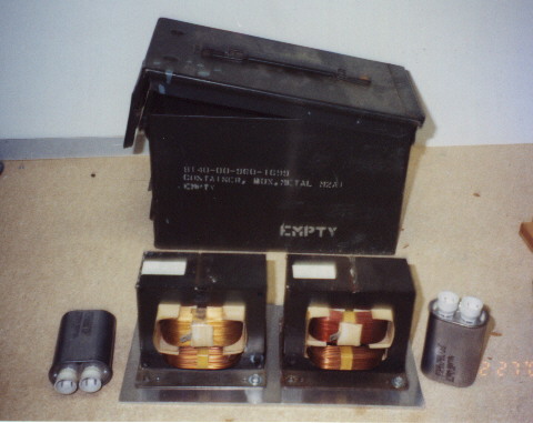
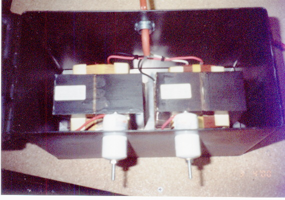
I've included some pictures so you can see how I put the thing together. The first image is a schematic diagram. The second image shows MOTs and capacitors. The next photo is the partly finished power supply with the lid open so you can see the layout. The third JPG shows the fully operational MOT power supply in the place of honor beside my two 9KV/60ma NSTs. The finished MOT supply is a compact, portable, self-contained unit. It is lighter and smaller than one of my 60ma NSTs, yet develops over 3KVA, more than twice the power of both NSTs put together.