This prject started with the idea to build a cheap inverter for our new house.
Cheap is relative ;)
$1600 has been spent on this project so far. I still dont believe you can
purchase a similarly rated inverter for that ammount.
This inverter was designed to last... I have used all new parts (the electrical
parts) which can be pricey in the small quantities I need.
the basic requirments
are:
1) Must be very very reliable, as it will run the whole house 24 hours a day.
2) Must be able to run a variety of loads... ranging from small motors up
to 3 phase 10HP wood working tools.
Preliminary Specs:
0) 15kw total output
power, 5KW per phase, 3 Phases
1) 48v battery bank
2) 120v RMS AC ouput (per phase)
3) 48v from batteries will be converted to positive and negative 170v DC at
80khz with ferrite transformer.
4) DC will then be converted into 120v AC with IGBT half bridge.
5) PWM carrier frequency will be 19khz
6) the carrier duty cycle will be modulated (PWM) to create a sine wave on
the output
7) the outputs will be aranged in the star configuration, so that 208v single
phase may be obtained
between any two phases.
8) The 19khz carrier frequency needs to be filtered out.
One PIC16F628 microcontrller will be used for each phase to generate the PWM signal from a lookup table. This method is very simple and straight foreward with few problems. One PIC16F628 is the master controller and the other two (slave phases) recieve a sync pulse from the master which tells them exactly when to reset the sine table.
There will be a main PIC16F77 controlling the inverter itself.. well mostly just watching over the other sections of the circuit to make sure it works right. If any values go above a preset the inverter will shut down and setoff an alarm.. This PIC is also responsible for driving a 4 line by 20 charicter LCD screen for data output.
RS-485 will link the inverter controller with two remote display panels (one as far as 800 feet) so I can watch over the state of charge in the batteries, charging current, output power.. ect... The RS-485 uses one twisted pair to transmit and recieve in half duplex mode, and two pairs in full duplex mode. It has a maxium distance of 4000 feet.
Schematic files:
Schematics Info: READ THIS I really would like to put them on here as pictures, but Splan just doesnt want to export them so they look good at decent sizes.. like fit on your screen size... BUT Splan does have its own standalone viewer which is available from the www.abacom-online.de website here is a link directly to the viewer in zip format: viewer download it is about 500kb.
-- Still preliminary, in active testing
-- These are direct links to the schematic files in .spl format, you should
right click and "save target as"
-- if this is really too hard and you would like me to put up images or pdfs
of the schematics... email me.
DC-DC converter full schematic
AC Inverter Simple schematic - Shows how a very simple single phase inverter can be implemented - not actaully used on my final design
Pin 9 of the PIC is the
PWM output pin.
Schematic Pictures -- only last resort... the Splan files are much better -- these may also be out of date (they are out of date)
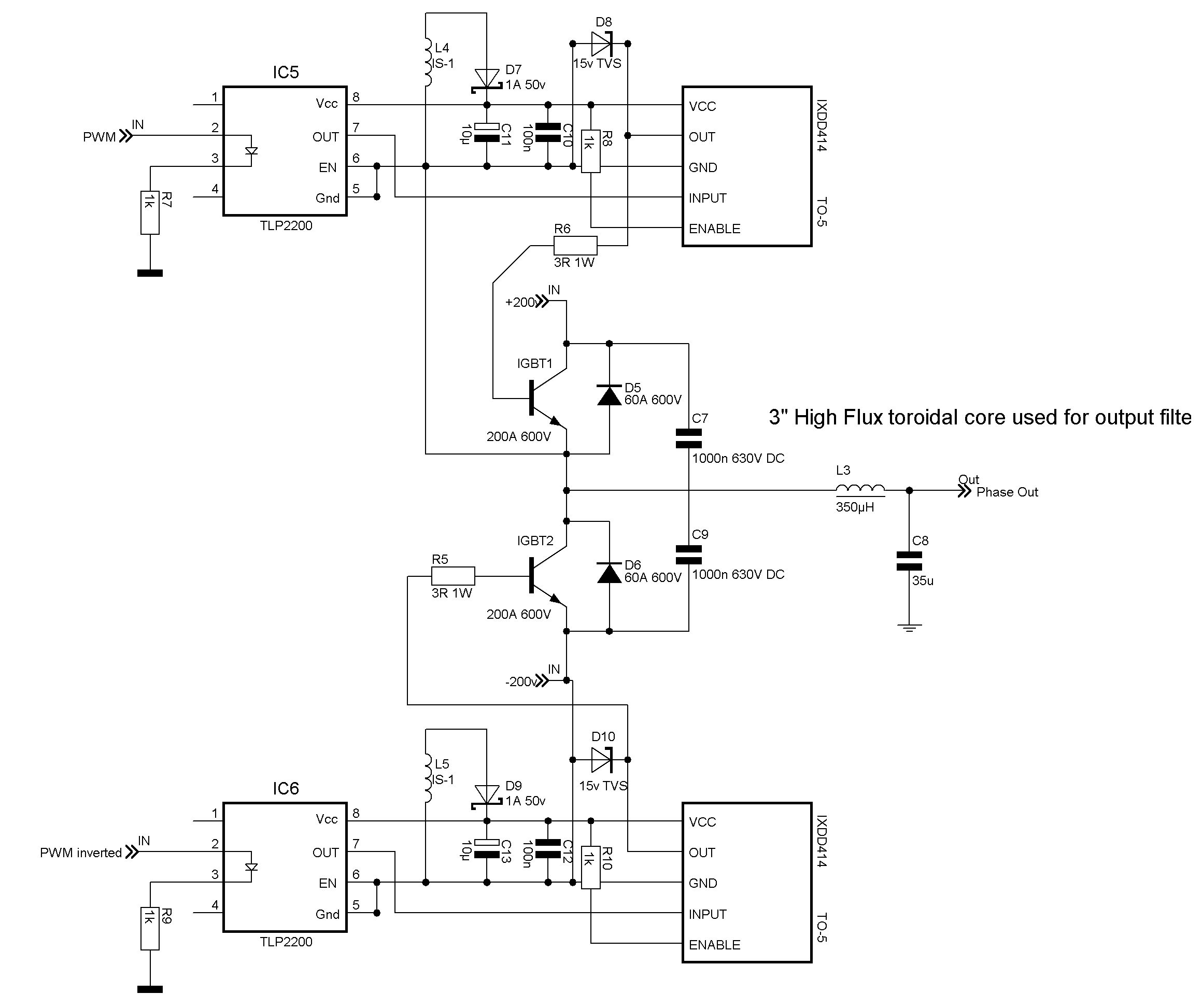
AC Inverter Power Half Bridge ~200kb
Board Designs
none yet
Construction Section:
1 KW Prototype DC-DC
Pictures:
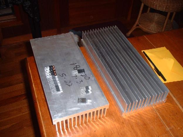
Large heatsinks I bought off Ebay.
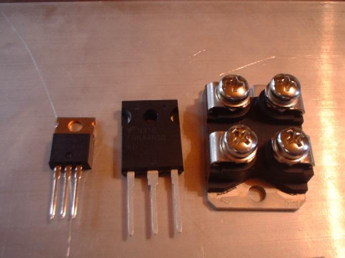
left is IRF1407(130A 75V), FDH44N50(44A 500V), GA200SA60U(200A 600V)
all 100 of my 200A 600V IGBTs.. let me know if you want to buy some for $8 each
All of my ideas/theories are open to question... this is by no means a finished project, im sure many faults will be discovered along the road.
hilo90mhz@hotmail.com -- all questions, comments, ideas, criticisms welcome