Lu Labs' Tesla Coil!
A Tesla coil is a high voltage, high frequency loosely coupled air-core resonant transformer. Most coilers (people who build Tesla coils)
build them for the sheer fun of watching the sparks fly!
I will not go into Tesla coil theory, as there is a lot on other sites. Click here for a great site detailing the operation of tesla coils.
Major Components:
Power Supply
Capacitor
Secondary Coil
Primary Coil
Spark Gap
Toroid
Control Box
Sparks!
Power Supply
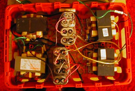
My power supply is a 4-pack MOT stack. It was made from 4 microwave oven transformers and 8 microwave oven capacitors, all salvaged from old microwave ovens. The supply is capacitatively limited to about 200mA, 2.5kVA. Output voltage is 12800 volts as measured with a DVM and a 21:1 voltage divider. It is having problems right now, I don't think that the output voltage is really 12800 volts since it only arcs 3-4mm. I will get around to fixing it sometime.
!!As of 5/20/03 the MOT stack is dead :-(
As of 6/19/03 the MOT stack has been fixed, awaiting testing... A new pic of the stack will be up as soon as I get my camera hooked up to the computer.
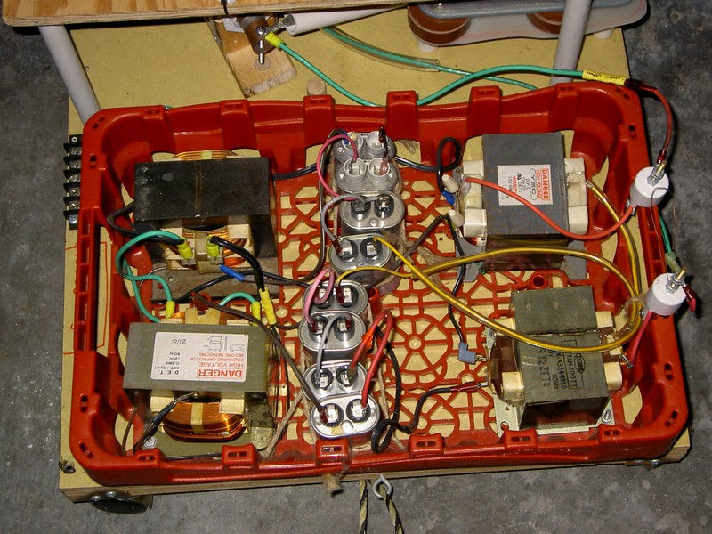
Here is a pic of the new MOT stack. The outer two MOTs were replaced, and some HV output bushings were made. There is a simple safety spark gap attached to one output bushing.
Capacitor
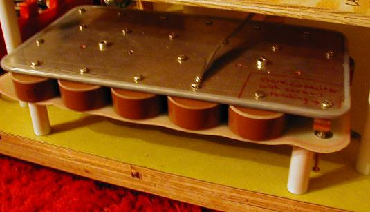
The main tank capacitor is 19 parallel TDK UHV-9A 2nF 40kV ceramic pulse-rated capacitors designed for use in lasers. The capacitors came from a random machine with no easily discernible function. There are 20 spaces on the aluminum mounting plates that serve as connection points. One space is not used, it is fitted with two screws that can be screwed together to short the capacitor for storage, and also serves as a saftey spark gap.
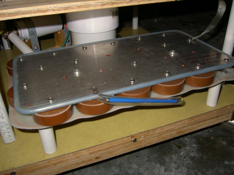
I now have a new cap bank as well. It consists of the same two aluminum plates except now with 17 TDK UHV 4nF 20kV capacitors, for a total of 68nF which brings the cap to a good LTR size. The safety gap has been adjusted for 20kV as well.
Secondary Coil
The secondary coil is 22AWG magnet wire close wound on 4in ID PVC pipe (4.5 inch OD). Winding length is 26 inches, coated first with Minwax fast drying polyurethane to soak into windings, then Helmsman spar urethane outer coats. Total: 6 coats of polyurethane.
Primary Coil
My primary is 1/4 inch soft refrigeration tubing wound on 1/2 inch PVC pipe supports and secured with cable ties (Greg Hunter's method: http://hot-streamer.com/greg/primary.htm This took me too long. Next time I will use HDPE supports that let the tubing snap into slots cut in the supports. On the other hand, it is very simple and requires only a drill, cable ties, and patience.
Spark Gap
The first spark gap is 2 3/4 inch copper pipes with end caps soldered on both ends. They are supported by wooden supports and insulated using PVC. It is unenclosed and will be air quenched by a leaf blower.
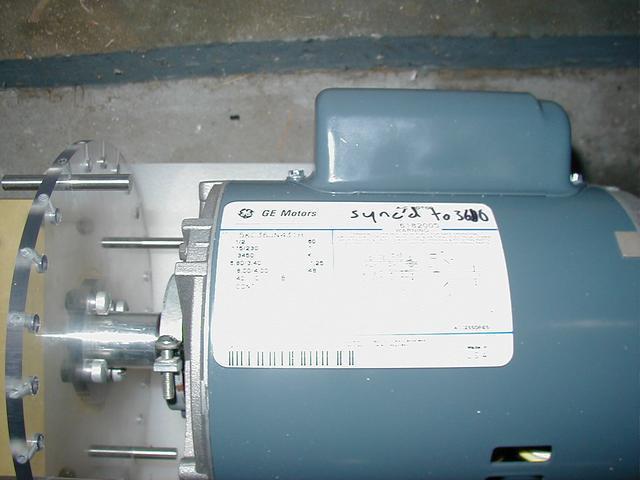
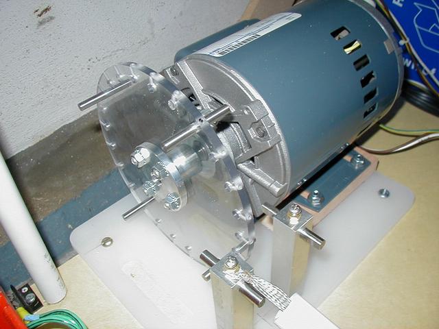
The second spark gap was a Synchronous Rotary Spark Gap (SRSG.) It has two stationary electrodes, up to 12 moving electrodes, a 7.5 inch by 1/4 inch thick Lexan disk, and a half-horsepower motor driving it all. The motor is a 3450RPM 1/2HP GE motor, with two flats milled on the rotor to make it synchronous at 3600RPM. The whole RSG works fine, I have to see if it is truly synchronous though. The addition of this spark gap made the coil operate strangely. It turns on for about 5 seconds, then shuts off for 10 seconds or so, then turns on again, etc... I don't know what might be causing this, if you know or think you know please contact me at kalenedrael "at" yahoo (dot) com.
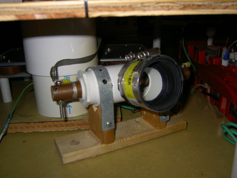
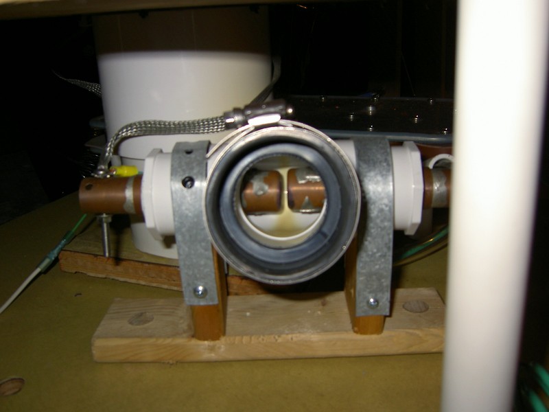
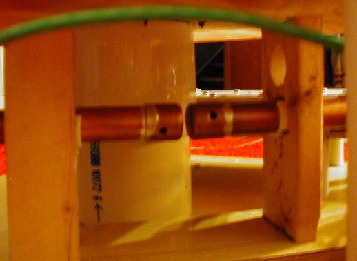
I now have another spark gap since the SRSG didn't work well and I had already trashed the first one. This is an "inside-out" sucker gap, so called since the "normal" sucker gap with the gap itself outside the tee has been turned "inside-out" so that the gap is inside the PVC tee. This allows the gap to be much smaller. What this gap consists of is two copper pipes that have endcaps with holes drilled in them as the gap faces. The vacuum cleaner attaches to the side outlet of the tee, and sucks air through the electrodes into the gap to blow out the spark. You can see in the photo of the inside that the UV and hot gases have caused some discoloration of the PVC. This will have to be remedied at some point, although it seems to be holding up fine.
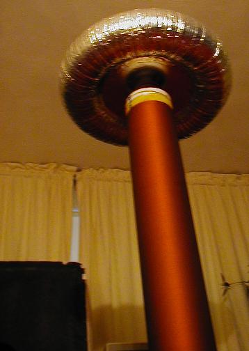
Toroid
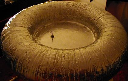
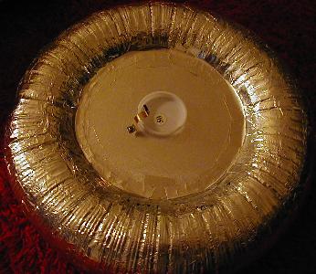
The first toroid was a crappy aluminum flex duct toroid wrapped with aluminum foil tape. It is a 16 inch major diameter by 4 inch minor diameter toroid with a capacitance that's too small for my coil. I need a bigger topload. The funky looking thing in the image to the right is the attachment mechanism to hold the toroid on the top of the secondary.
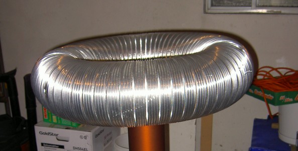
I now have a bigger topload, a 6 by 30, which still is a bit too small since I still get multiple streamers. I have some more flex duct that I plan to make another toroid out of and put it on top.
Control Box
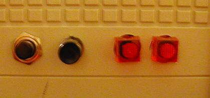
A random box that I had lying around was converted into a simple control box. The four things in the image are, from left to right: a start switch, a kill switch, and 2 indicator lights (one for each side of the 240 volt line.) Inside is a terminal strip, a line filter, and a relay.
NEW! I have a new control box that is plastic and so the case isn't LIVE (which got on my nerves, pun intended) when operating. I learned that the old one was live the hard way... It was only about 10-20 volts or so, because the case was connected to neutral and the MOTs had different impedances. The new pic will be coming soon.
First Light!!!
The coil works! Spark images can be found here
New spark images and a movie can be found here with the names new-spark-x.xxx
Thanks to:
Terry Fritz for being my web host :-)
Ray Harlan for doing the machining work for my Rotary Spark Gap
The All Things Tesla forum run by Jim Layton for TONS of information that made my Tesla coil possible
The Tesla Coil Mailing List
Greg Hunter for his excellent web site loaded with information on Tesla coiling