![]()
![]()
Central Science Club
Project Tesla Coil 2004
Background
10/04
This project started in the Fall of the 2004 school year at Central High School in La Crosse, WI under the supervision of physics teach Joe Anglehart. A year earlier students expressed interest in building a coil after seeing a small demonstration coil I built. Now we have been meeting on a weekly basis to get the students up to speed on theory of operation so we can start making some hypotheses and incorporating them in our design. The purpose of my guidance in the project is simply to help with construction so there are no serious accidents or wrong turns resulting in a dead project. I'm really looking forward to see what kind of ideas these guys come up with .
11/04
Okay, we've finally settled on a design and have begun construction. Our design is somewhat modeled after Greg's 6-inch coil. However, we decided to use a OBIT farm along with a SRSG in the tank circuit. The reason for these changes are 1.) We can get quite a few OBITs by asking around town and 2.) A Sync Rotary Spark Gap is somewhat unpredictable. These two design changes reflect our major design goals: we want a coil whose behavior is predictable and reliable while at the same time being economical.
Construction Photos
Session #1
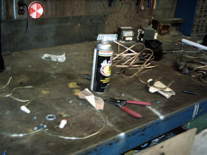
We began construction in Jake's garage... here is the mess of parts we started with.

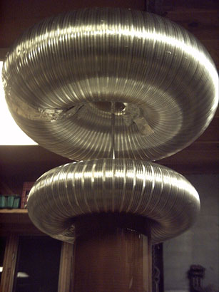
As you can see the first order of business was to re-arrange our dryer duct into a topload. Obviously it won't be big enough, but we plan on experimenting with different shaped toploads and this will provide somewhat of a starting point.
Here Tyler preps the secondary coil former. It's a 6"ID 6-3/4" OD PVC pipe 33 inches long.

Test fit of the toriod. So far so good.

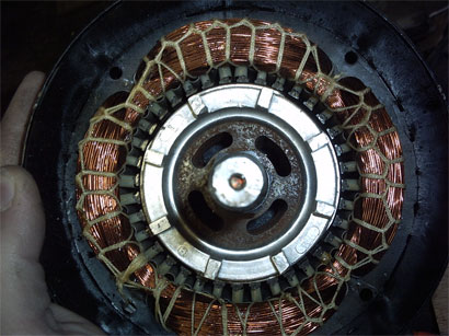
Here we have the wire, (which we obtained from Lackore Electric Motor Repair with an "education discount" -thanks guys) 22 gage about 2lbs, a test transformer 15kV @ 30mA, and our SRSG motor with it's armature out for modification.

Jack, our trigonometry expert lays out the supports on what will be the top level of our coil.

Jake makes some temporary wooden "endcaps" for winding the secondary, while Jack takes a break from laying out the primary to maintain sanity (it really is a lot harder than it looks to lay out 6 supports evenly without any really accurate way of finding 30 or 60 degree incriments).

Finished laying out the supports, halfway through cutting out the upper deck.

Testing our neon sign transformer. Crummy picture.
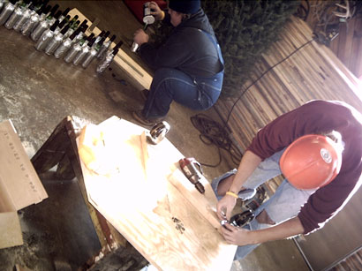
Jack and Devon ambiguously marking some cuts for primary coil supports.

Marking out where the holes will go on the primary coil supports. It's kind of tedious, but with a section of steel "U" channel, marking along the pipes' axis was simplified and the result was pretty well within tolerance (i.e. they didn't look like we made them during and earthquake).

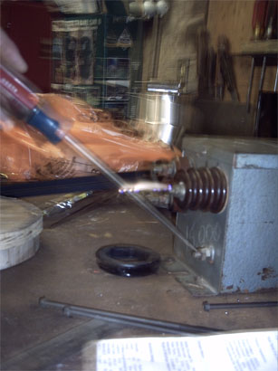
Motor armature back in it's natural habitat. If you look closely you can see the four flats lined up with the "dead" poles of the motor (under the start windings). I used a belt sander with a 220 grit belt to remove enough material so the flats would be 1/3 the diameter of the armature (the motor was 1745 RPM, now 1800 RPM, Salient pole so the electrodes will align at the peak of capacitor charge).
Some wood inserts being attached to the finished primary coil for the secondary coil to slide onto so it will sit slightly above the plane of the primary. The pieces that will be inside the inner turns will be doweled in place so there's no chance of stray corona.
Really nice job on that primary guys... hats off to ya.
Session #2
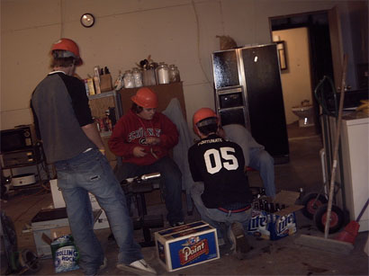
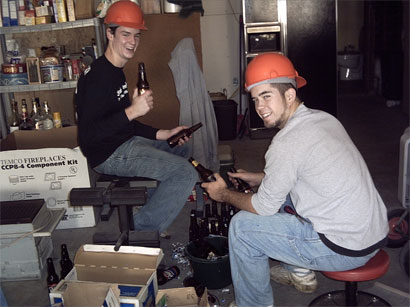
The guys in suitable Tesla Coil rated safety gear.
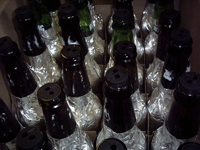
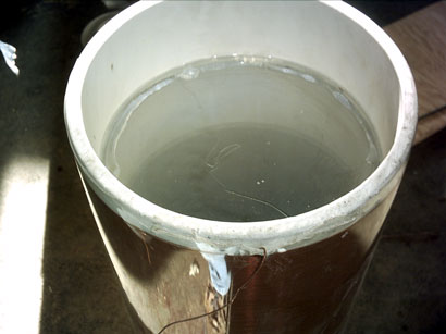
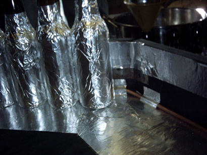
At this point I think clarification may be needed. Thanks to some generous donors, we aquired a couple cases of empty beer bottles to use for our capacitor.
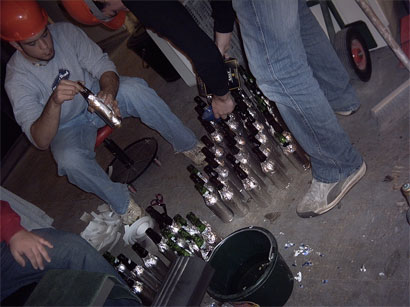
After a couple hours of removing lables and taping foil to the sides of the bottles, it's now time to add salt. Still in search of a cheap supply of corks or rubber stoppers to plug the tops and act as a feed through for the wires.
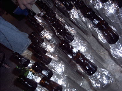
We made a sample bottle cap and tested it at 10kV with/without an inductive load and we concluded that a 3 inch margin to the top of the bottles will be sufficient to prevent arcing. I'm personally surprised the margin is that small. In my first coil the margin was no less than 4 inches with a 12kV transformer.
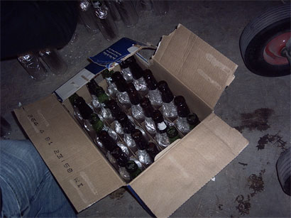
1 Bank down...
Session #3
Thanks to Mr. Anglehart for hooking us up with these beautiful two-hole number 2 rubber stoppers to support the conductors while keeping the fluid in our saltwater capacitors. We can now wire capacitor to capacitor neatly. Sure beats glueing or shaping another miscellaneous object to accomplish this task.
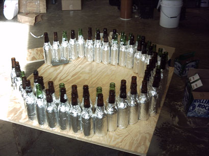
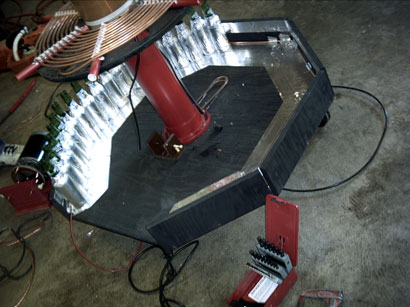
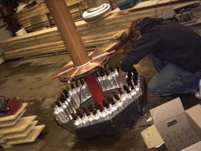
Doing a test to see what shape we want to make our lower deck. The idea here is to encompass the bottom of the coil with the capcitors, creating a glowing ring of corona. For those of you who haven't used salt water capacitors, they sizzle with corona along the foil edges - why not show it off?
Ty and Jake hard at work. The primary deck gets some casters to make moving it's ever increasing girth while the last of the bottles get salted. We're going to wait with the water till the wires are put in with the stoppers. This way, the hot water used to dissolve the salt will cause a pressure drop when the air/water inside cools. If and when the air inside the bottles decides to expand, there should be a fair amount of headroom.
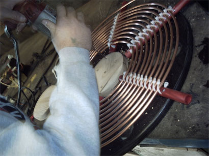
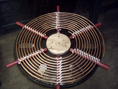
I had to get a shot of this nice primary. We shamelessly stole Greg's idea to mount the tubing, but hey - it was a good idea. Those cable ties are hooked end to end through the holes - another nice little innovation by the guys in the hard hats. We're keeping the slack after the last turn for now: Perhaps it will reach down and make the connection to the salt water caps. In that case the primary would be tapped inside-out. We'll see...
Jake cut out these 1/4" thick plexiglass circles and we epoxied them in either end of the coil to prevent racing arcs inside the former. I've never had problems with interior racing arcs before, but ever since I first read about them I have been keeping the practice of sealing the secondary's insides with a non-flammable sealer (i.e. don't use pvc glue, rubber roofing chaulk, or acrylic glue because they will fill the inside of the coil with flammable vapors.)
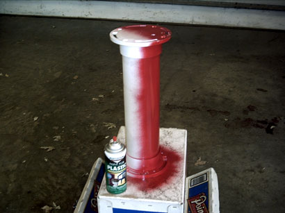
Here's the center column that will support the upper deck with the primary/secondary. It's being coated with a red vinyl dye to keep with our school color theme. The column is a 4 inch sched 40 PVC pipe glued to two "johnny flanges."
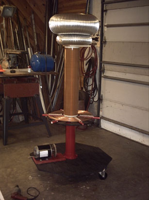
It's really starting to look like a Tesla coil. It's fun throwing the components together from time to time to get an idea of the progress we've made. If you're a coiler, you know what this is all about. There is a lot of work involved in the production of a coil and it's a bit of a morale booster to see it starting to take shape.
Sessions #4&5
Halfway through session 4 the guys seemed a bit discouraged with the seemingly endless number of tasks that were left to be completed. To remedy this, I suggested we put together what we have and make some sparks as a bit of a motivator. With 2 OBITs and 14 bottle capacitors and all our primary, we were able to get 6" sparks from our smaller topload. I think it was a very successful morale booster.
We put in about 3 hours in session 4 and the group is now ready to get down to business and push through the final steps to get this coil off the ground.
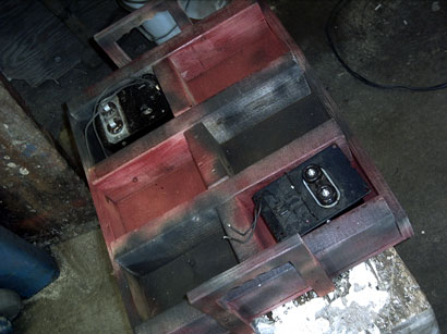
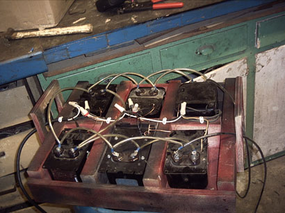
Here's the product of most of session 4 - a 6 bay OBIT holder complete with carrying handles. We wanted to keep the transformers separate from the rest of the coil to cut down on it's overall weight. With the salt water capacitors, it's heavy enough. The plan with this arrangement is to find as many OBITs, like the near one in the picture, as we can. That way, the low voltage connections can be made down the middle, with each transformer properly grounded, and use insulated jumpers with crimp connections for the high voltage along each side. Then two main HV leads would exit the two far corners in the picture, while the main power cord would enter through the near handle so there's little chance of primary side to secondary side arcing.
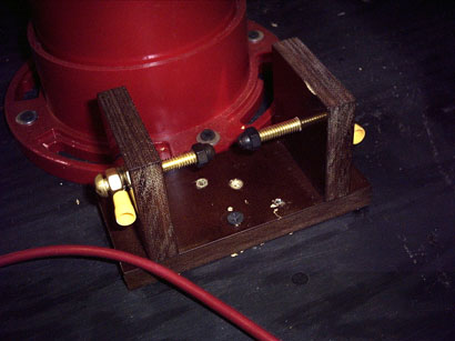
Here's the overvoltage gap I made. It's 1/2" thick phenolic with brass 1/4-20 electrodes. A slight mishap occurred, ( then reoccurred : ) while mount this to the base. Phenolic acts kind of like really sappy wood when you want to run a screw through it. If you want the screw to survive, the pre-drilled hole must be larger than usual to cut down on friction. Here it wouldn't have hurt to make the hole bigger than the threads altogether. Oh well - not all of our group members have spent their entire highschool career in between the wood and metal shop like I did ;-)
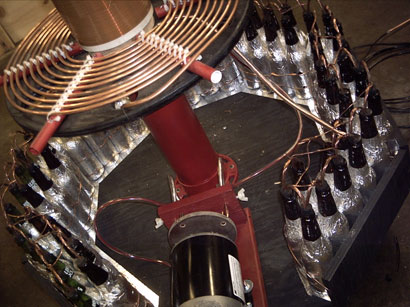
The capacitors getting all lined up and connections being made.
A close up of the connections between the foil of the bottles. This isn't exactly ideal when it comes to good connections. But we did what we could with the materials we had. Yes, that's foil tape under and behind the bottles - the layers were folded over so the conductive sides would be touching, not just the adhesive backing. There's a 1/4" copper tube that runs around the outside which contacts both the foil channel and the foil on the bottles themselves. Then, at one end there's a 10 gage machine tool wire crimped in the end. 10 gage machine tool wire was chosen for the tank wiring because I had some, and because it's the best combination of flexibility and conductivity as far as wires are concerned. The stuff appears to be made of tons of 30 or 32 gage copper strands covered either in aluminum or silver.
I got a hold of some scrap #6 stranded copper grounding wire to make the connections between the tops of the salt water capacitors. This string measured 0.2 Ohms - I think that's acceptable. We simply went from bottle to bottle and twisted the wires on the inside. Unfortunately, we have 67 bottles so far, and if each bottle takes about a foot of material, that's a lot of copper - which is not cheap now. Luckily, I offered to buy some scrap from a local electrician, which was a good deal for the both of us. We get terrible rates for recycling scrap copper around here- like $0.30/lb - and when it comes to new ground wire, it costs at least twice that per foot. All you have to do to get some peices like we need is offer a better price than scrap, and everybody wins.
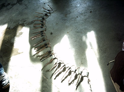
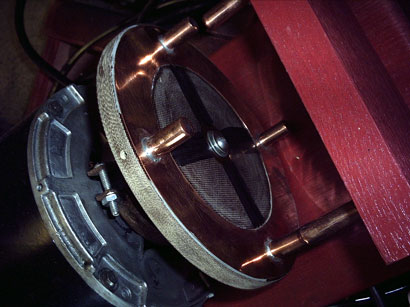
Here's a shot of the SRSG rotor I made. The electrodes and ring are made of solid copper soldered together. This was a total pain in the butt to make. The rotor and electrodes took me 6 hours to make, most of which was spent at the drill press polishing the copper. I really like how copper polishes up - I didn't have to do this, but a mirror shine on the electrodes really knocks the spark gap up a notch as far as appearance is concerned.
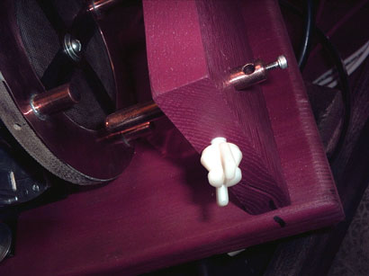
Here's the stationary electrodes. I think this picture is quite self-explanatory, but I'll go into it a bit for the non-coilers reading this. The nylon screws on the side are for quick adjustments. The electrodes are pretty much press fit into the wood, but they will move without too much of a fuss, so I added the set screws to keep them from vibrating into the motor. The holes on the ends are for the tank circuit wire to be clamped into. In this picture you can see the hole where the grub screws go in on the rotor to hold the electrodes in place although they are really tightly press fit into place.
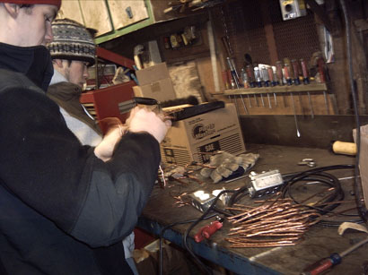
Please excuse the poor picture. I was in the middle of making the connections for the OBITs. I had to use a spray lubricant to get the wires into the insulation. I used clear plastic airline tubing to insulate the HV wires - it stands off a large amount of voltage and I got 20 feet of it for $1.50.
It may seem like I was doing lots of work this time. However, I was doing a bit of recap some stuff I forgot to mention earlier and the guys were working on the salt water capacitor bank. Don't let anyone fool you - salt water capacitors are simple and easy to make individually - but if you want a large bank of them, you'll have to put in a fair amount of work.
Till next time we meet, we're going in search of more transformers. I'm currently working on a simple remote switch/extension cord so we don't have to mess around plugging and unplugging stuff.
All that remains as of this point in time is fabricate the topload assembly, finish wiring the capacitors, and put together the OBIT bank. My guess is that at the end of the next two sessions we'll be able to run full power.
Session #6
Not too much to say this time... still working on the capacitors.
There's a lot of connections to be made. When all's said and done, the capacitor should be in the ballpark of 55nF - that's LTR. Where resonant cap size is about 40nF. That much capacitance should require about nine turns on our primary - which is ideal.
Here we are all wired up.
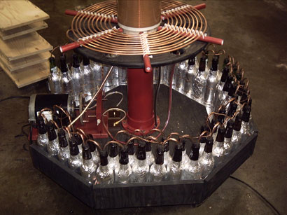
Another view. The HV connections will come in next to the motor and land on the safety gap.
Here's the power supply unit (PSU), all wired and ready to go. Six OBITs add up to about 1500 Watts (10kV @ 150mA).
The topload sits on a 1/4" metal rod and a whole lot of aluminum tape.
Setting up in the dark. It's really cold so the rest of the spectators are sticking close to the garage.
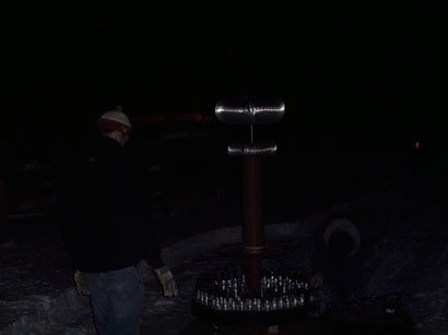
First full power run:
We tuned and tweaked for a while, but the best sparks so far have only been about a foot long. I was messing with spark gap timing, spacing, and primary taps with little improvements. On the last run I set the spark gap too small and the electrodes collided. The piece of oak that held each electrode was broken in half and the electrodes are slightly marred. Sure I spent a lot of time on the gap, but since it wasn't performing all that well I'm not going to lose any sleep over it. In fact, I suspect that the spark gap is the biggest problem.
Therefore..... I have an idea. All the guys in the science club will be designing their own spark gap in somewhat of a contest. Hopefully we'll see some new ideas - but right now I'm sure we'd settle for one that works well ;-)
Till then...
Updates soon to come... we are currently doing work on pretty much a weekly basis, so check back soon.
Note: The "sessions" are ~4 hour periods on weekends. Some work does take place between these times throughout the week but usually don't get documented. I am kicking myself for not recording the times and dates when stuff was worked on. It's really difficult to convey a sense of how long things take and the scattered process of acquiring parts and assembly.