The Vortex Gap

Revisited...
The Vortex Gap
Revisited...
Fellow coiler Gary Lau came up with the idea of using a vortex to quench a spark gap in his design which can be found here. He documented a "17.5% reduction in gap losses" with his setup, which I found quite impressive. However, I noticed some areas in which his idea could be taken further.
First you've got to know what makes this gap different from a traditional air blast gap. Of course, it's the "vortex." Before we go on to actually employing a vortex in a spark gap, let's look at what they are and how they can be useful to us. I define a vortex as a rotating air mass with a low pressure center. Air molecules enter a spiral path as they approach and are drawn toward the area of low pressure at the core. When the air molecules are headed toward the center, something interesting takes place. The molecules accelerate due to the conservation of angular momentum.
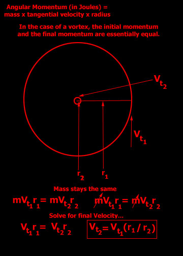
Note that the final momentum is "essentially" equal to the initial momentum. In a small vortex like this, the air molecules don't have much time to lose energy, but as you increase the size of the aparatus, the effect is diffused by turbulence and cohesion of the air against the sides of the chamber. Thus, there is likely a practical limit to which we can see the same linear relationship to the size of the vortex and it's resulting air speed.
To illustrate what is taking place in our gaps, I have drawn some cross sections, detailing the center of the vortex. The thin red lines represent paths taken by various air molecules that started out in our cross sectional plane, but since their motion is three dimensional, it is important to note that they are still circling the center, not just flying past it.
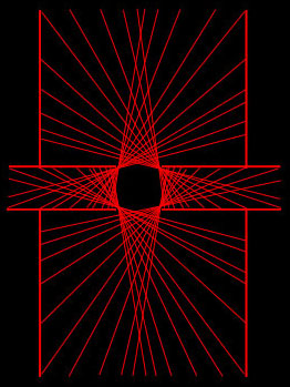
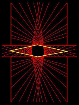
It's difficult to draw what's going on here without using some 3D simulation, but my drawings show the basic idea. The yellow lines highlight the low pressure cavity inside the electrodes which the air molecules are attracted to and consequently, orbit. Note that the lines that appear to go through this region do not - they pass behind it - but that's more difficult for me to illustrate.
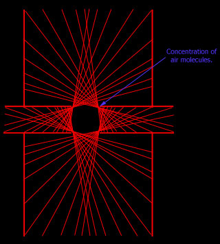
There are spots where the air tends to concentrate - near the edges of our electrodes - this happens to be quite convenient for quenching purposes.
Here's a quick drawing of my estimation of the first vortex gap prototype:
While this gap has proven effective, I feel there is room for improvement.
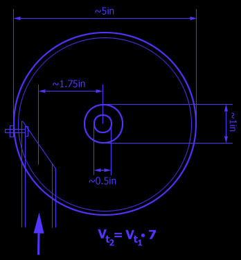
First and foremost is the small size of the device. It's a good thing to conserve space, but if there is more performance to be had, I would be willing to scale things up a bit. To keep things reasonable, let's try an outer diameter of 12 inches. While we're increasing the size, we might as well improve the shape while we're at it. The PVC tube protruding into a circle is a bit rough. Perhaps a gradual spiral curve could allow air to enter the vortex more freely and with less turbulance. Although heat dissipation and wear are factors to be considered for the electrodes, they could benefit from being smaller. Reducing their size would be no problem since there will be fast moving air covering their inner surfaces at all times.
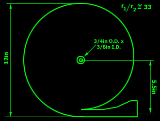
My revised version will be constructed with wood, and will be similar to the following drawing.
So far, all I have completed are the electrodes...
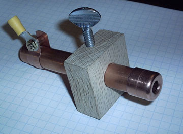
It's just a 1/2 inch rigid copper stub with a drilled/polished end cap. The O.D. of the cap is a little shy of 3/4" and the inner dimension is a bit smaller than 3/8". The thumb screw is to allow easy adjustment of the gap width. The connection was made with a regular plumber's copper strap bent all the way around the pipe and bolted to a crimp terminal for final connection. The adjustable mount is made of oak because I will be gluing them to the wooden sides of the vortex chamber with polyurethane glue. I am aiming to make the whole thing very solid to try and trap the noise, and inadvertently, the harsh UV light.
UPDATE: MARCH 2005
So I finally got around to working on this thing. I have been busy with work and personal stuff lately, but at last I have something to show you.
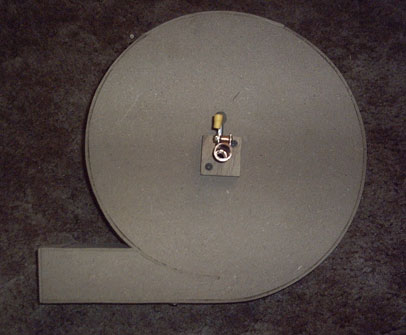
Here's my prototype model. Not the prettiest, but I just tried hard enough to not want to kill myself if/when it doesn't work or starts on fire.
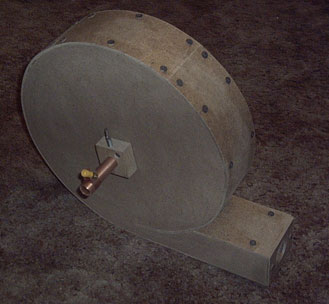
Side view - you can see the nice smooth transition of the radius to avoid turbulence.
Top access panel for eyeballing the spacing. I hope I can figure out another way to set the spacing so I won't have to dissassemble stuff to make a "quick" adjustment. That could make the tuning process a bit aggrevating.
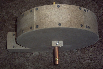
The inlet is 1-1/4" to fit the hose of a 2 HP ShopVac. I have a vacuum motor and turbine, but it's awaiting a housing, but this will be good enough for a test.
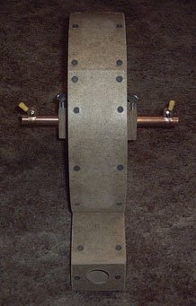
The whole deal is made of MDF that I had left over from a subwoofer project. That stuff can be finicky to work with, but the end result is pretty solid and should do a great job of trapping noise and light. Although I do expect some light and sound will be coming through the exhaust. If it works well enough maybe I'll make a couple little mufflers for it ;-)