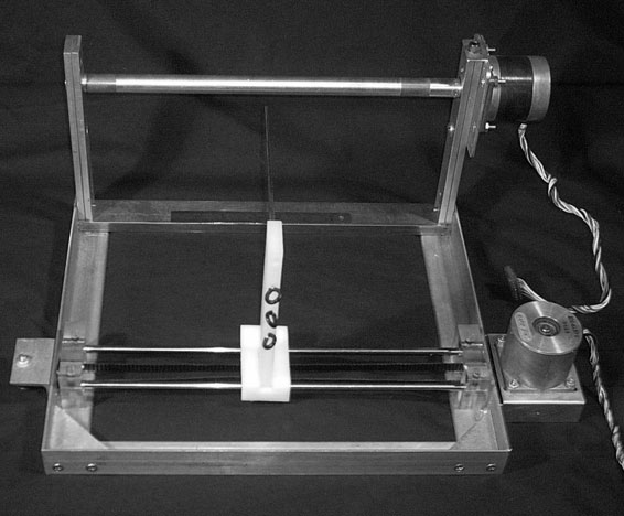
Transformer Winder Project
I started this project in the spring of 2002 and shelved the idea a few months later. My goal was to create a semi-automatic transformer secondary winder. Other coilers such as Terry Fritz and James Cart have done projects like this which helped serve as a starting point for my design. Links to their projects can be seen at the bottom of the page. Why create an automated winder? Using a hand drill to wind a Tesla coil secondary is tedious enough. Multiply the number of turns by 20 and reduce the wire size to the size of a human hair. The process of winding one's own transformer is often referred to as "not worth it," "insane," or "foolish" to the common garage coiler. This is my solution.
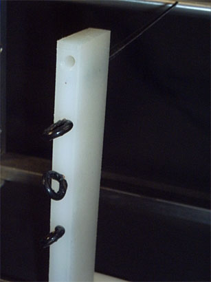
Oh yeah, that ruler is 6.75 inches from end to end, for an idea of scale.
I must take a moment and make a very important note. To those of you who are thinking of doing a similar project - THIS IS NOT THE EASIEST WAY. My project is not completely about winding transformers. It's more about learning how to make an accurate, user-friendly, and useful machine using programmable microcontrollers. If I really just wanted to make a transformer, I would make a very simple, hand operated device like the one used by Finn Hammer. I asked James Cart what he would have done differently and he told me he would make his hand driven as well. A computer controlled winder is a much bigger can of worms than what is necessary. Just don't say I didn't warn you.
Now some detailed photos (sorry, none of the construction)....
Here's the wire guide assembly. It's made of HDPE and UHMWHDPE (plastic). The wire will go through the series of black loops, through the hole in the top of the plastic, and down the end of the pointer where it will meet the former. The "pointer" is actually just a section of antenna with the end cut off. This arrangement allows me to use different diameter coils with a simple adjustment. Wire tension is acheived by turning the black loops while the wire is in the guide. This makes the route more diffucult for the wire to travel without adding too much friction. I may decide to use something inside the rings to add friction if this doesn't do the trick.
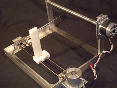
The main spindle is mounted on a set of sealed ball bearings so there is very little friction.
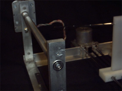
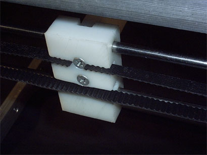
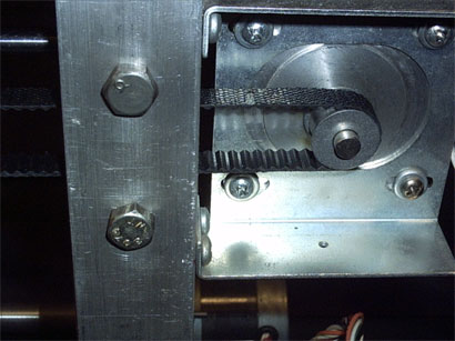
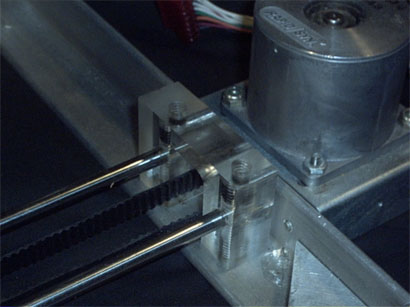
Detailed view showing how the wire guide assembly is attached to my homemade cog belt. It's cut from a strip of rubber door mat I got at Ace Hardware for like 10 cents.
I mounted the motor on it's own removable plate so all that is required to detach it is to remove the thumbscrew on top, and the wingnut under the motor. One thing I've learned through winding many Tesla coil secondaries is that it really helps to be able to easily remove your coil (especially when it's been wound with fragile 34 gage wire).
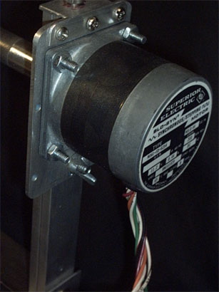
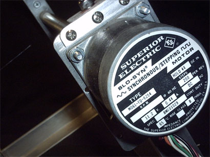
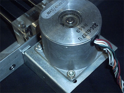
A Close up of the main drive motor. I'm not sure there will be enough torque but I would still like to use it. If the main drive motor rate is variable, a finer degree of turn to turn spacing can be attained. Although in retrospect, I think Terry's leadscrew stylus is a better way to acheive that result.
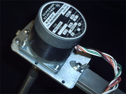
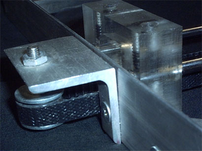
A quick shot of the motor mount that controls tension on the belt. Just loosen the screws from underneath and slide the motor over to adjust.
My homemade pulley on the opposite end. It's made of screws/nuts/bolts/misc stuff from my scrap collection. Not too bad for a frankenstein lashup.
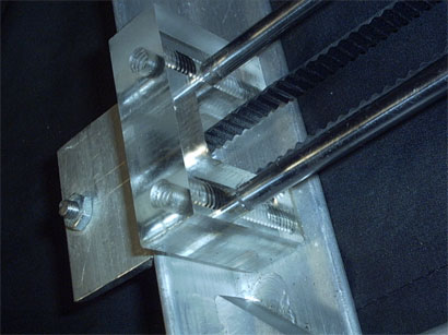
The blocks that hold the transversal rods was machined on my drill press using a milling bit to carve out the middle for the belt to run through. It was no easy task though - especially with how tempermental acrylic can be. The rods are 1/4" cold rolled steel that I sanded/polished and the acrylic is 3/4" thick sheet.
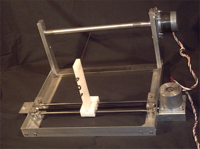
The whole project eagerly awaiting her brain...
Future Developments
The plan so far is to use a couple of PIC 16F84 programmable microcontrollers to be the logical control center. I'm thinking cooking up a circuit to allow control of wire spacing through the use of a rotary switch with different values of resistors that vary the step rate of the main motor. I'm also looking into getting a LCD. There are many sites out there that show how to interface with the common hitachi driver chip. I'd like to have a 2 line display that showed the "status," whether the coil was being wound right or left, paused or finished, the current "layer" and the number of completed "turns". I think that would provide adequate information to the user during the winding process. Also an alarm might be useful to let the operator know when a layer has been completed so that insulation can be added.
There's a lot of experimenting and planning left to do. I'll try to keep this page up to date as progress continues.
Right now I'm waiting on my PIC programmer kit... I ordered it two weeks ago and I'm still waiting for the "shipping confirmation email" that "Circuit Specialists, Inc." promised. Bad business guys.
Links
Terry Fritz' Winder: HTML or ZIP
James' Winder: James' Homepage or Direct link