Best heard with 32+ bit wave table sound cards.
Wild Bill Emery and I attempted an oil
filled magnifier in late '96. We used a 24-inch length of 12-inch PVC as
the container for the oil. The secondary was a special commercial coil out
of an industrial transformer. It was about 4 inches in diameter, and was
wound with 6-gauge flat enamel wire. What was weird about this winding, is
that the flat enamel wire was wound on edge, greatly increasing the
turns-per-inch. We used 3 inch wide copper strap as a primary, and covered
the secondary with 22 pounds of Mylar before wrapping the primary on. The
primary was 8 turns, and had 60-mil polyethylene between turns. The electrical
ground and power connections through the wall of the 12-inch PVC pipe were
made by attaching brass water faucets through the walls of the pipe. The
brass faucets provided low impedance connections, and had the benefit of
screw-on and screw-off connections.
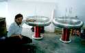
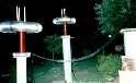
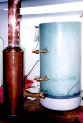
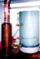 [20k] On the left is the 6 gauge secondary. On the right is the 12-inch
diameter PVC pipe container. Note the three brass faucet connectors for
ground and primary power.
[20k] On the left is the 6 gauge secondary. On the right is the 12-inch
diameter PVC pipe container. Note the three brass faucet connectors for
ground and primary power.
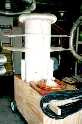
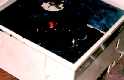
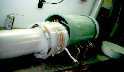 [18k] Detail of magnifier during assembly. Note the poly between primary
turns and taps. Secondary was insulated with 22 pounds of mylar.
[18k] Detail of magnifier during assembly. Note the poly between primary
turns and taps. Secondary was insulated with 22 pounds of mylar.
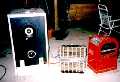
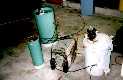 [26k] Oil-filed magnifier set up on garage floor for testing. Visible are
driver, pole pig, rotary and capacitor.
[26k] Oil-filed magnifier set up on garage floor for testing. Visible are
driver, pole pig, rotary and capacitor.
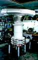
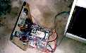
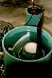 [21k] Driver with transformer oil in place. Note the massive secondary
copper electrode rising off the top of the secondary.
[21k] Driver with transformer oil in place. Note the massive secondary
copper electrode rising off the top of the secondary.
The next magnifier that Bill Emery and I worked on was modeled on
Richard Hull's 11-E driver. We wound a 16-inch diameter PVC pipe with
10-gauge wire and made a primary out of coax. We mounted a sheet of plywood
on six legs and started refining the system.
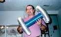
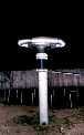
 [28k] Early magnifier driver. Toroids were stored on top of driver when
not in use, but obviously were not used as shown, but they sure make a
real cool looking picture! We called this the Moon-Lander.
[28k] Early magnifier driver. Toroids were stored on top of driver when
not in use, but obviously were not used as shown, but they sure make a
real cool looking picture! We called this the Moon-Lander.
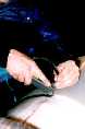 [15k] We initially insulated the driver secondary with Mylar, but a
carbon edging caused a short. Here, Bill is cutting away the carbon edging
on the Mylar. Note the HV carbon arc in the poly from the top of the coil
to the carbon edge on the Mylar. We later found Mylar conducts very high
voltage anyway, so we abandoned using Mylar as a driver insulation.
[15k] We initially insulated the driver secondary with Mylar, but a
carbon edging caused a short. Here, Bill is cutting away the carbon edging
on the Mylar. Note the HV carbon arc in the poly from the top of the coil
to the carbon edge on the Mylar. We later found Mylar conducts very high
voltage anyway, so we abandoned using Mylar as a driver insulation.
 [28k] This is our "Mary Poppins" driver configuration. Named after the
two 120 mil poly "umbrellas". We were having severe arcs from the top
corona ring to the primary, and the two plastic shields were designed to
prevent the arcs. Rope putty caulk was used to seal the disks to the poly
insulation cylinder around the secondary. To our surprise, we got no arcs
from the top of the secondary (approximately 250 kV), but we did get a lot
of arcs from the primary to the poly cylinder which then traveled on the
surface of the poly upwards to the putty seal rings. We removed both disks
and cleaned the rope caulk off the poly cylinder.
[28k] This is our "Mary Poppins" driver configuration. Named after the
two 120 mil poly "umbrellas". We were having severe arcs from the top
corona ring to the primary, and the two plastic shields were designed to
prevent the arcs. Rope putty caulk was used to seal the disks to the poly
insulation cylinder around the secondary. To our surprise, we got no arcs
from the top of the secondary (approximately 250 kV), but we did get a lot
of arcs from the primary to the poly cylinder which then traveled on the
surface of the poly upwards to the putty seal rings. We removed both disks
and cleaned the rope caulk off the poly cylinder.
 [30k] Wild Bill showing tunable primary, which has pivots on each vertical
upright post. Tilting primary posts, as shown, brings turns closer
together.
[30k] Wild Bill showing tunable primary, which has pivots on each vertical
upright post. Tilting primary posts, as shown, brings turns closer
together.
 [23k] Bert Pool, holding the "Blue Goose" extra coil. Similar to Richard
Hull's "E" coil, 13 inches long, 4 in diameter, wound with 30 gauge Kynar
insulated wire-wrap type wire. The corona rings/small toroids are supposed
to provide field shaping. Unfortunately, we found them to be far too small
to be effective.
[23k] Bert Pool, holding the "Blue Goose" extra coil. Similar to Richard
Hull's "E" coil, 13 inches long, 4 in diameter, wound with 30 gauge Kynar
insulated wire-wrap type wire. The corona rings/small toroids are supposed
to provide field shaping. Unfortunately, we found them to be far too small
to be effective.
 [13k] Blue Goose in action. Note the 6-foot arc on the left to a grounded
rod. There are violent arcs from the top ring to bottom ring. There were
also arcs from the windings themselves. We may eventually return to this small
coil, but with improved larger toroids.
[13k] Blue Goose in action. Note the 6-foot arc on the left to a grounded
rod. There are violent arcs from the top ring to bottom ring. There were
also arcs from the windings themselves. We may eventually return to this small
coil, but with improved larger toroids.
 [22k] Current magnifier coil (8-97), 10.8 inches diameter, 24 inches long,
two layers of 18 gauge magnet wire. Note the three PVC pipes used to hold
toroids in place. Bill Emery and Bert Pool have pioneered multi-layer coils,
both extra coils and driver secondary coils. Our current driver secondary uses
four layers of wire!
[22k] Current magnifier coil (8-97), 10.8 inches diameter, 24 inches long,
two layers of 18 gauge magnet wire. Note the three PVC pipes used to hold
toroids in place. Bill Emery and Bert Pool have pioneered multi-layer coils,
both extra coils and driver secondary coils. Our current driver secondary uses
four layers of wire!
 [21k] Jerry Gore with two magnifier extra coils. One coil is a single layer
coil, the other is a two layer coil. The coils were wound in opposite
directions to test an idea on a twin magnifier concept.
[21k] Jerry Gore with two magnifier extra coils. One coil is a single layer
coil, the other is a two layer coil. The coils were wound in opposite
directions to test an idea on a twin magnifier concept.
 [20k] Jerry Gore showing how the three PVC rods can be used to safely stack
toroids for more capacitance. Toroids are spaced with a 10 inch PVC pipe
spacer.
[20k] Jerry Gore showing how the three PVC rods can be used to safely stack
toroids for more capacitance. Toroids are spaced with a 10 inch PVC pipe
spacer.
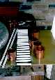
 [26k] Bert working on power controller for magnifier. Main variac can handle
up to 80-amps at 240 volts.
[26k] Bert working on power controller for magnifier. Main variac can handle
up to 80-amps at 240 volts.
 [33k] This is Bill Emery bypassing the 80-amp variac after it smoked one
night! We currently are running our magnifiers with only inductive and
resistive ballasts and NO variacs, with excellent results.
[33k] This is Bill Emery bypassing the 80-amp variac after it smoked one
night! We currently are running our magnifiers with only inductive and
resistive ballasts and NO variacs, with excellent results.
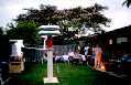
 [26k] Typical power setup on back patio. Power cabinet on left, heater
ballasts in middle and welder on right.
[26k] Typical power setup on back patio. Power cabinet on left, heater
ballasts in middle and welder on right.
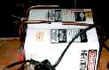
 [28k] Top view of power controller electronics. Contactors, power supply
for contactors, and variac for spark gap motor are mounted on panel. Meters
and switches are on top of cabinet.
[28k] Top view of power controller electronics. Contactors, power supply
for contactors, and variac for spark gap motor are mounted on panel. Meters
and switches are on top of cabinet.
 [20k] This is a close-up of a current meter, which we re-wound to work with
the current transformer that we had on hand. Amp meters use large gauge wire,
and can be reworked if found to be not quite what you need.
[20k] This is a close-up of a current meter, which we re-wound to work with
the current transformer that we had on hand. Amp meters use large gauge wire,
and can be reworked if found to be not quite what you need.
 [23k] Maxwell impulse caps with impromptu safety gaps made from 1/4 inch
copper tubing. Always put safety gaps across your caps!
[23k] Maxwell impulse caps with impromptu safety gaps made from 1/4 inch
copper tubing. Always put safety gaps across your caps!
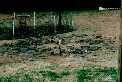 [36k] Triangular ground system is buried here. Note the copper strap sticking
out of the ground. Six ground rods were driven into the ground and connected
with 2 inch wide copper strap soldered to the copper clad rods.
[36k] Triangular ground system is buried here. Note the copper strap sticking
out of the ground. Six ground rods were driven into the ground and connected
with 2 inch wide copper strap soldered to the copper clad rods.
 [19k] First copper cylinder series spark gap that we built, using five
2-inch diameter cylinders. Note the much larger 2.5 inch cylinder to the
left.
[19k] First copper cylinder series spark gap that we built, using five
2-inch diameter cylinders. Note the much larger 2.5 inch cylinder to the
left.
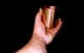 [10k] Scale pic showing just how large a 2.5-inch cylinder really is.
 [26k] Large cylinder gap under construction. Cylinders sit on white
fiberglass rods.
[26k] Large cylinder gap under construction. Cylinders sit on white
fiberglass rods.
 [16k] Blue Goose with 62 inch toroid.
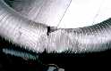 [22k] Damaged 62-inch by 8-inch toroid, which was blown off an extra coil.
Aluminum duct toroids cannot withstand much abuse.
[22k] Damaged 62-inch by 8-inch toroid, which was blown off an extra coil.
Aluminum duct toroids cannot withstand much abuse.
 [22k] Magnifier driver on right, extra coils on left. Note the flat
aluminum flashing transmission line, a "first' pioneered by Wild Bill and
Bert Pool. The flashing does not produce measurable corona. The far coil
was connected with coax, but the attempt at a twin magnifier coil did not
work well.
[22k] Magnifier driver on right, extra coils on left. Note the flat
aluminum flashing transmission line, a "first' pioneered by Wild Bill and
Bert Pool. The flashing does not produce measurable corona. The far coil
was connected with coax, but the attempt at a twin magnifier coil did not
work well.
 [27k] Magnifier in operation. The extra coil on the left was not powered,
but was seen as a grounded object.
[27k] Magnifier in operation. The extra coil on the left was not powered,
but was seen as a grounded object.
 [20k] Early magnifier runs.
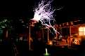
 [28k] Our favorite magnifier picture, June '97.
On June 28th, 1997, we had a large run of the magnifier in the
back yard. Below are a series of photos from that evening.
 [18k] Wild Bill and Jerry Gore bless Jerry's "immaculate Construction"
coil.
[18k] Wild Bill and Jerry Gore bless Jerry's "immaculate Construction"
coil.
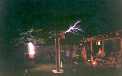
 [23k] Early dusk shot; we were tuning the coil.
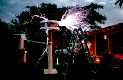
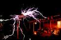
 [30k] Violent shorts on driver coil and extra coil indicate out-of-tune
condition.
[30k] Violent shorts on driver coil and extra coil indicate out-of-tune
condition.
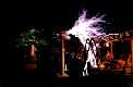
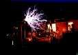
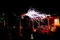
 [24k] Late dusk, good sparks using two 36 inch toroids.
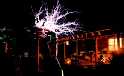
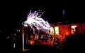
 [20k] Another breakdown due to incorrect tuning. Note reduced output.
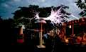
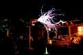
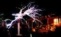
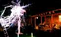
 [21k] Excellent photo of twin toroids in full tuned operation.
 [19k] Striking citronella candle exactly 15 feet from toroid.
 [18k] Striking concrete patio somewhere beyond 15 foot candle.
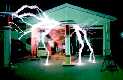
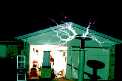
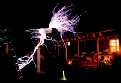
 [22k] Nice ladder strikes and roof hit.
 [21k] Strike to fluorescent tube stuck in grass.
 [23k] Solid hits to ladder.
 [16k] Heavy hits to roof. Note Jerry Gore standing of roof with camera
near strikes.
[16k] Heavy hits to roof. Note Jerry Gore standing of roof with camera
near strikes.
 [19k] Run with 62-inch toroid.
 [17k] Ladder hits from 62-inch toroid, good example of wind blowing out
sparks.
[17k] Ladder hits from 62-inch toroid, good example of wind blowing out
sparks.
 [18k] Many roof hits from 62-inch toroid.
 [16k] Heavy ladder strikes with Jerry Gore on roof taking 3-D photos.
[22k] More roof and ladder hits.
 [24k] Storey Clamp and Matt Gutting visit Ft. Worth.
 [26k] Very violent ladder ravaging when wind let up.
 [20k] Bill climbing into cut-off piece of 28.5 inch diameter PVC pipe.
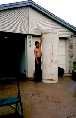 [21k] Wild Bill standing next to 7 foot tall, 28.5 inch diameter PVC pipe
to be used for upcoming monster coil. This is to be wound with 10 gauge
enamel wire. Stay tuned!
[21k] Wild Bill standing next to 7 foot tall, 28.5 inch diameter PVC pipe
to be used for upcoming monster coil. This is to be wound with 10 gauge
enamel wire. Stay tuned!
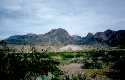 [27k] Mountains of Big Bend National Park, south Texas, USA, spring '97.
No big sparks, except when God gets out his big coil.
[27k] Mountains of Big Bend National Park, south Texas, USA, spring '97.
No big sparks, except when God gets out his big coil.
 [20k] On the left is the 6 gauge secondary. On the right is the 12-inch
diameter PVC pipe container. Note the three brass faucet connectors for
ground and primary power.
[20k] On the left is the 6 gauge secondary. On the right is the 12-inch
diameter PVC pipe container. Note the three brass faucet connectors for
ground and primary power. [10k] Scale pic showing just how large a 2.5-inch cylinder really is.
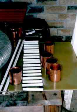 [26k] Large cylinder gap under construction. Cylinders sit on white
fiberglass rods.
[26k] Large cylinder gap under construction. Cylinders sit on white
fiberglass rods.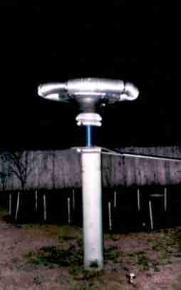 [16k] Blue Goose with 62 inch toroid.
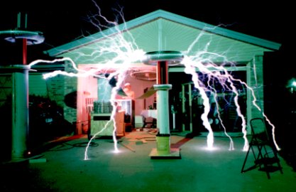 [28k] Our favorite magnifier picture, June '97.
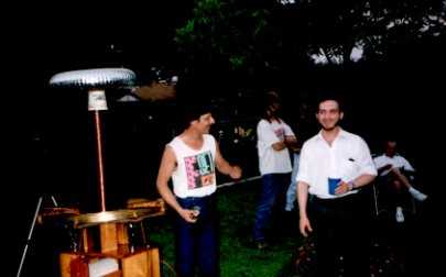 [18k] Wild Bill and Jerry Gore bless Jerry's "immaculate Construction"
coil.
[18k] Wild Bill and Jerry Gore bless Jerry's "immaculate Construction"
coil.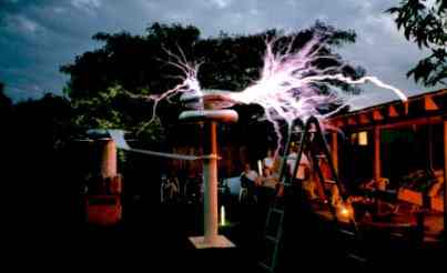 [23k] Early dusk shot; we were tuning the coil.
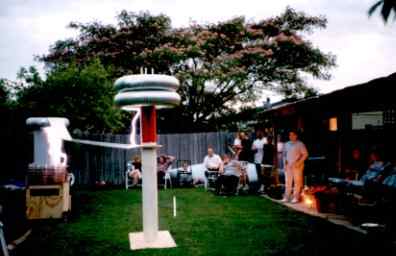 [30k] Violent shorts on driver coil and extra coil indicate out-of-tune
condition.
[30k] Violent shorts on driver coil and extra coil indicate out-of-tune
condition.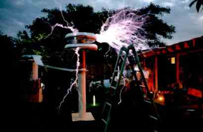 [24k] Late dusk, good sparks using two 36 inch toroids.
 [20k] Another breakdown due to incorrect tuning. Note reduced output.
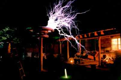 [21k] Excellent photo of twin toroids in full tuned operation.
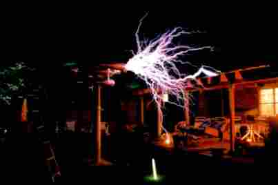 [19k] Striking citronella candle exactly 15 feet from toroid.
 [18k] Striking concrete patio somewhere beyond 15 foot candle.
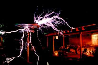 [22k] Nice ladder strikes and roof hit.
 [16k] Heavy hits to roof. Note Jerry Gore standing of roof with camera
near strikes.
[16k] Heavy hits to roof. Note Jerry Gore standing of roof with camera
near strikes.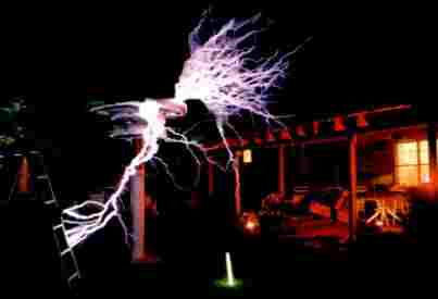 [19k] Run with 62-inch toroid.
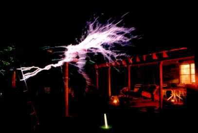 [17k] Ladder hits from 62-inch toroid, good example of wind blowing out
sparks.
[17k] Ladder hits from 62-inch toroid, good example of wind blowing out
sparks.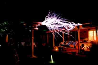 [18k] Many roof hits from 62-inch toroid.
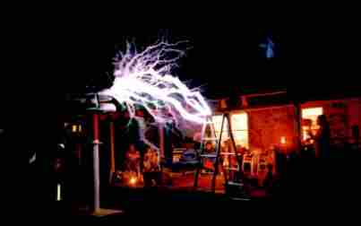 [16k] Heavy ladder strikes with Jerry Gore on roof taking 3-D photos.
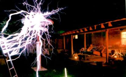 [26k] Very violent ladder ravaging when wind let up.
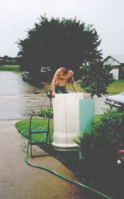 [20k] Bill climbing into cut-off piece of 28.5 inch diameter PVC pipe.
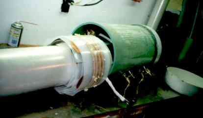 [18k] Detail of magnifier during assembly. Note the poly between primary
turns and taps. Secondary was insulated with 22 pounds of mylar.
[18k] Detail of magnifier during assembly. Note the poly between primary
turns and taps. Secondary was insulated with 22 pounds of mylar.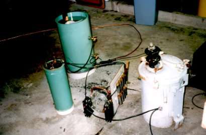 [26k] Oil-filed magnifier set up on garage floor for testing. Visible are
driver, pole pig, rotary and capacitor.
[26k] Oil-filed magnifier set up on garage floor for testing. Visible are
driver, pole pig, rotary and capacitor.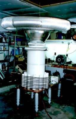 [28k] Early magnifier driver. Toroids were stored on top of driver when
not in use, but obviously were not used as shown, but they sure make a
real cool looking picture! We called this the Moon-Lander.
[28k] Early magnifier driver. Toroids were stored on top of driver when
not in use, but obviously were not used as shown, but they sure make a
real cool looking picture! We called this the Moon-Lander.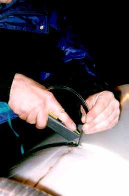 [15k] We initially insulated the driver secondary with Mylar, but a
carbon edging caused a short. Here, Bill is cutting away the carbon edging
on the Mylar. Note the HV carbon arc in the poly from the top of the coil
to the carbon edge on the Mylar. We later found Mylar conducts very high
voltage anyway, so we abandoned using Mylar as a driver insulation.
[15k] We initially insulated the driver secondary with Mylar, but a
carbon edging caused a short. Here, Bill is cutting away the carbon edging
on the Mylar. Note the HV carbon arc in the poly from the top of the coil
to the carbon edge on the Mylar. We later found Mylar conducts very high
voltage anyway, so we abandoned using Mylar as a driver insulation.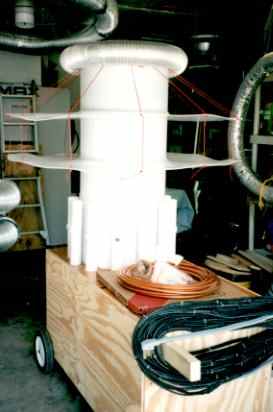 [28k] This is our "Mary Poppins" driver configuration. Named after the
two 120 mil poly "umbrellas". We were having severe arcs from the top
corona ring to the primary, and the two plastic shields were designed to
prevent the arcs. Rope putty caulk was used to seal the disks to the poly
insulation cylinder around the secondary. To our surprise, we got no arcs
from the top of the secondary (approximately 250 kV), but we did get a lot
of arcs from the primary to the poly cylinder which then traveled on the
surface of the poly upwards to the putty seal rings. We removed both disks
and cleaned the rope caulk off the poly cylinder.
[28k] This is our "Mary Poppins" driver configuration. Named after the
two 120 mil poly "umbrellas". We were having severe arcs from the top
corona ring to the primary, and the two plastic shields were designed to
prevent the arcs. Rope putty caulk was used to seal the disks to the poly
insulation cylinder around the secondary. To our surprise, we got no arcs
from the top of the secondary (approximately 250 kV), but we did get a lot
of arcs from the primary to the poly cylinder which then traveled on the
surface of the poly upwards to the putty seal rings. We removed both disks
and cleaned the rope caulk off the poly cylinder.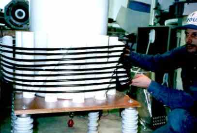 [30k] Wild Bill showing tunable primary, which has pivots on each vertical
upright post. Tilting primary posts, as shown, brings turns closer
together.
[30k] Wild Bill showing tunable primary, which has pivots on each vertical
upright post. Tilting primary posts, as shown, brings turns closer
together.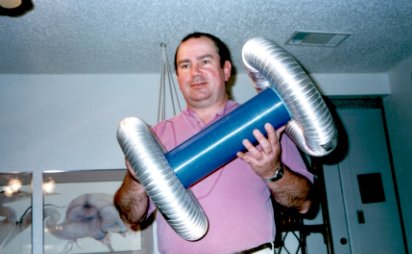 [23k] Bert Pool, holding the "Blue Goose" extra coil. Similar to Richard
Hull's "E" coil, 13 inches long, 4 in diameter, wound with 30 gauge Kynar
insulated wire-wrap type wire. The corona rings/small toroids are supposed
to provide field shaping. Unfortunately, we found them to be far too small
to be effective.
[23k] Bert Pool, holding the "Blue Goose" extra coil. Similar to Richard
Hull's "E" coil, 13 inches long, 4 in diameter, wound with 30 gauge Kynar
insulated wire-wrap type wire. The corona rings/small toroids are supposed
to provide field shaping. Unfortunately, we found them to be far too small
to be effective.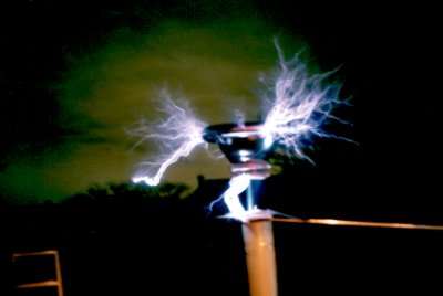 [13k] Blue Goose in action. Note the 6-foot arc on the left to a grounded
rod. There are violent arcs from the top ring to bottom ring. There were
also arcs from the windings themselves. We may eventually return to this small
coil, but with improved larger toroids.
[13k] Blue Goose in action. Note the 6-foot arc on the left to a grounded
rod. There are violent arcs from the top ring to bottom ring. There were
also arcs from the windings themselves. We may eventually return to this small
coil, but with improved larger toroids.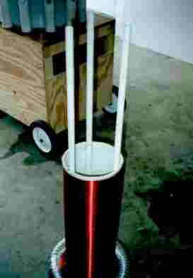 [22k] Current magnifier coil (8-97), 10.8 inches diameter, 24 inches long,
two layers of 18 gauge magnet wire. Note the three PVC pipes used to hold
toroids in place. Bill Emery and Bert Pool have pioneered multi-layer coils,
both extra coils and driver secondary coils. Our current driver secondary uses
four layers of wire!
[22k] Current magnifier coil (8-97), 10.8 inches diameter, 24 inches long,
two layers of 18 gauge magnet wire. Note the three PVC pipes used to hold
toroids in place. Bill Emery and Bert Pool have pioneered multi-layer coils,
both extra coils and driver secondary coils. Our current driver secondary uses
four layers of wire!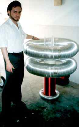 [20k] Jerry Gore showing how the three PVC rods can be used to safely stack
toroids for more capacitance. Toroids are spaced with a 10 inch PVC pipe
spacer.
[20k] Jerry Gore showing how the three PVC rods can be used to safely stack
toroids for more capacitance. Toroids are spaced with a 10 inch PVC pipe
spacer.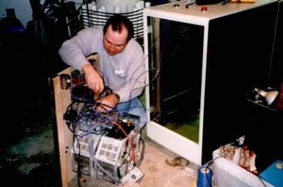 [26k] Bert working on power controller for magnifier. Main variac can handle
up to 80-amps at 240 volts.
[26k] Bert working on power controller for magnifier. Main variac can handle
up to 80-amps at 240 volts.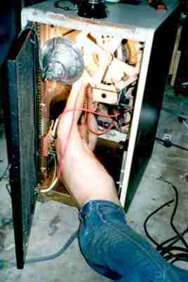 [33k] This is Bill Emery bypassing the 80-amp variac after it smoked one
night! We currently are running our magnifiers with only inductive and
resistive ballasts and NO variacs, with excellent results.
[33k] This is Bill Emery bypassing the 80-amp variac after it smoked one
night! We currently are running our magnifiers with only inductive and
resistive ballasts and NO variacs, with excellent results. [26k] Typical power setup on back patio. Power cabinet on left, heater
ballasts in middle and welder on right.
[26k] Typical power setup on back patio. Power cabinet on left, heater
ballasts in middle and welder on right. 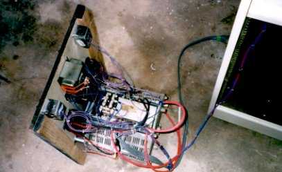 [28k] Top view of power controller electronics. Contactors, power supply
for contactors, and variac for spark gap motor are mounted on panel. Meters
and switches are on top of cabinet.
[28k] Top view of power controller electronics. Contactors, power supply
for contactors, and variac for spark gap motor are mounted on panel. Meters
and switches are on top of cabinet. [20k] This is a close-up of a current meter, which we re-wound to work with
the current transformer that we had on hand. Amp meters use large gauge wire,
and can be reworked if found to be not quite what you need.
[20k] This is a close-up of a current meter, which we re-wound to work with
the current transformer that we had on hand. Amp meters use large gauge wire,
and can be reworked if found to be not quite what you need.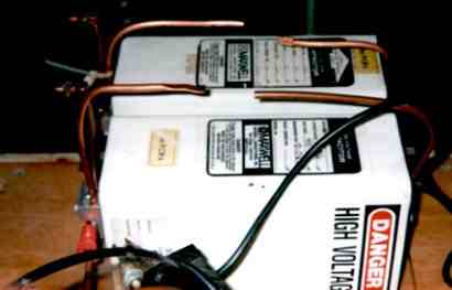 [23k] Maxwell impulse caps with impromptu safety gaps made from 1/4 inch
copper tubing. Always put safety gaps across your caps!
[23k] Maxwell impulse caps with impromptu safety gaps made from 1/4 inch
copper tubing. Always put safety gaps across your caps!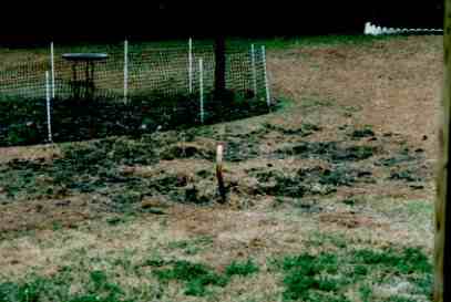 [36k] Triangular ground system is buried here. Note the copper strap sticking
out of the ground. Six ground rods were driven into the ground and connected
with 2 inch wide copper strap soldered to the copper clad rods.
[36k] Triangular ground system is buried here. Note the copper strap sticking
out of the ground. Six ground rods were driven into the ground and connected
with 2 inch wide copper strap soldered to the copper clad rods. 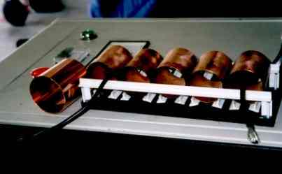 [19k] First copper cylinder series spark gap that we built, using five
2-inch diameter cylinders. Note the much larger 2.5 inch cylinder to the
left.
[19k] First copper cylinder series spark gap that we built, using five
2-inch diameter cylinders. Note the much larger 2.5 inch cylinder to the
left.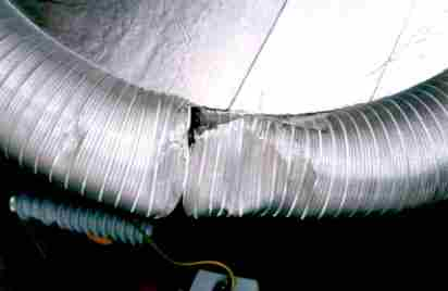 [22k] Damaged 62-inch by 8-inch toroid, which was blown off an extra coil.
Aluminum duct toroids cannot withstand much abuse.
[22k] Damaged 62-inch by 8-inch toroid, which was blown off an extra coil.
Aluminum duct toroids cannot withstand much abuse.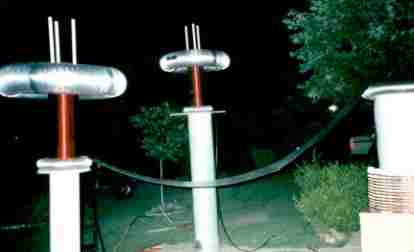 [22k] Magnifier driver on right, extra coils on left. Note the flat
aluminum flashing transmission line, a "first' pioneered by Wild Bill and
Bert Pool. The flashing does not produce measurable corona. The far coil
was connected with coax, but the attempt at a twin magnifier coil did not
work well.
[22k] Magnifier driver on right, extra coils on left. Note the flat
aluminum flashing transmission line, a "first' pioneered by Wild Bill and
Bert Pool. The flashing does not produce measurable corona. The far coil
was connected with coax, but the attempt at a twin magnifier coil did not
work well.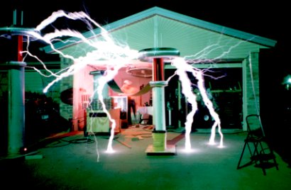 [27k] Magnifier in operation. The extra coil on the left was not powered,
but was seen as a grounded object.
[27k] Magnifier in operation. The extra coil on the left was not powered,
but was seen as a grounded object.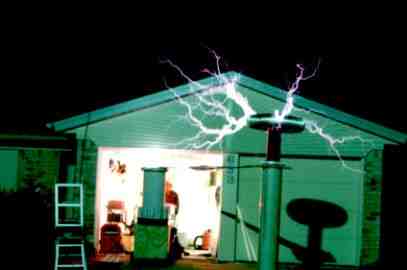 [20k] Early magnifier runs.
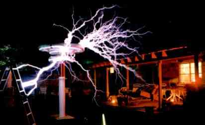 [23k] Solid hits to ladder.
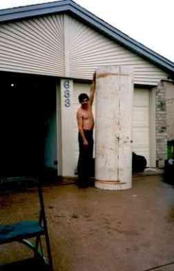 [21k] Wild Bill standing next to 7 foot tall, 28.5 inch diameter PVC pipe
to be used for upcoming monster coil. This is to be wound with 10 gauge
enamel wire. Stay tuned!
[21k] Wild Bill standing next to 7 foot tall, 28.5 inch diameter PVC pipe
to be used for upcoming monster coil. This is to be wound with 10 gauge
enamel wire. Stay tuned!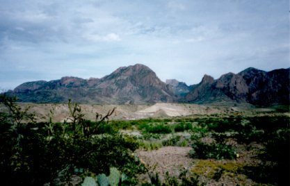 [27k] Mountains of Big Bend National Park, south Texas, USA, spring '97.
No big sparks, except when God gets out his big coil.
[27k] Mountains of Big Bend National Park, south Texas, USA, spring '97.
No big sparks, except when God gets out his big coil.