Vacuum Tube Tesla Coil

[ Summary Page | Details Page ]


A rough draft of some 3CX2500 stuff.  9/18/2001  

All Pics are "Clickable"

3cx2500_proto.jpg (61323 bytes)   3cx_arcs.jpg (45807 bytes)  101-0127_img.jpg (78323 bytes)
Overview of 3cx2500 setup.  1 sec time exposure pic shows 27-28" arcs.
The voltage was about 4500VAC and I don't know plate current b/c it slams my 1A meter.  Probably 1.5-2A.
Finally made a power controller.  Nothing too fancy, just prevents powering up the plate before the filament and has a remote deadman switch  for the High Voltage.


tube_rectify.gif (13774 bytes)
You can clearly see that the tube is only working during the positive half cycle


plate_grid.gif (12394 bytes)
This is a screen grab of the Tek TDS210 with a 15KV probe on the plate and another 15KV probe on the grid.
Q:  What should the grid V look like under ideal circumstances???
A:  A reasonable person would assume that the grid V would look just like the Primary V since they are coupled.  I found that the unusual shape of the grid voltage resulted from too many turns on the grid leak coil.  After I backed down on the number of turns, the waveforn started to look sinusoidal.


Schematic for 3-1000Z Power Oscillator wired for AC Mode Operation


Most Recent Component Values - see txt below for more complete description

VR1:  7.5K adj, 100W  C2:  5nF, 2500VDC, mica L2:  3 turns of 1/2" cu strap, 0.5" dia
C1:  3.5 nF, 30KV "doorknob" C(p):  1.2 nF +/- 0.2 nF R2:  Unknown, probably 50 ohm, 5W
C3:  9.3nF, 9600VDC, MMC L(p):   

TEST LOG  (Reverse Chronological Order)    
All pictures are "clickable" for a larger view

4/29/01
VTTC Model 3-1000z is DEAD.  I burned a hole in the side of the plate while driving the tube insanely beyond its ratings.  More details coming soon.  See the following pics until I have time to clean up this site.  It's a shame the tube died.  I feel like I was really understanding "best practices" in building this configuration of VTTC. 

You can see the death (execution) here:  http://hot-streamer.com/temp/deaththrows.mov
Warning - 10MB file will take ~40 mins to download at typical 56K speeds.

Note the new primary with multiple taps, new toroid, and primary former that extends the length of the secondary to allow for easy tuning of the grid coil position.

dead_system.jpg (43481 bytes)
First and Last Run of New system
28_inches.jpg (26383 bytes)
28" arcs shortly before the hole melted in the plate
hole_in_plate.jpg (49873 bytes)
Hole in the plate
4/04/01
(1) increased the max input to the plate tranny from 140V to 280V.  This will allow me to get up to 5 KVAC out of the plate transformer
(2) replaced the wimpy. burned out 7Kohm grid leak resistor with a 200W, 1000 ohm variable resistor.
(3) Noticed that about 750 ohms of resistance in the grid leak R seems to clamp I(grid) at around 250ma

I managed to get 24" arcs to a ground rod with the increased tube voltage!
Here is a short video of my VTTC making the 24" arcs.  Warning:  it is about 6MB and will take 20-30 mins to load with a 56k modem.
3/18/01
(1) Removed the 50 ohm resistor that was in line between the grid coil and the grid.
(2) Removed the choke on the filament transformer.  Now use CT for gnd.  Placed capacitors between each leg and CT.
(3) Mounted my blower to the base.  Plumbed it to the tube base with 2" PVC.
(4) Made a cute lexan stand for the plate current and grid current meters.

Observations:
The first experiment involved reducing the grid coil from 10T to 6T.  The coil still likes to run at almost a dead short for grid-leak R and still likes to have the grid coil far away from the primary.  I did an experiment where I taped the 6T grid coil to a lexan stick and removed it from the primary former.  This allows me to raise it about 10" above the primary if I want.  There was an obvious peak where I(plate) and arcs were at a maximum.  This point was about 2" above the top of the primary former or about 5 inches seperating the grid coil and the primary coil.  I also managed to get the grid coil too close to the secondary and had a bad flash over.  Damage to secondary appears to be minor.

----- Here are some stats using the 6T grid coil placed about 3" above the primary -----
grid leak R = 5-8 ohms
Arc = 15"
V(plate) = 2680 VAC
I(plate) = 700ma
I(grid) = 320ma
arc dropped to 6" with grid leak R at 100 ohms

grid leak R = 16 ohms
Arc = 15" (same...)
V(plate) = 2680 VAC (same...)
I(plate) = 660ma
I(grid) = 280ma
the coil behaved about the same at reduced power throughput

----- Since the 6T grid coil burned up in the accident, I install the 16T grid coil -----
grid leak R = 1.5K ohms
Arc = 15"
V(plate) = 2680 VAC
I(plate) = 500ma
I(grid) = 320ma
note that I get the same arc lenght at less power.  arcs look thinner that those listed above.  I moved the variable C from it max to its min position and my arcs went from 6" to 15"!  The coil seems to be really sensitive to tuning with this combo of grid turns and grid-leak R.  I didn't find the peak so that probably means that I should reduce my primary turns to raise the resonant freq.  I really would like to see a peak as I cross F(res).

Misc.
Damn blower motor is getting so hot I'm afraid its going to fail soon.  I measured the current at 2.2A unloaded and about 2A with it attached to the plumbing.  I figured the back pressure may be dropping its RPMs and making it heat up so I cut a hole in side of the PVC pipe.  A large amount of air now blows out the side but suprisingly about the same amount goes around the tube.  The heating problem didn't get much better with the addition of the extra blow by.

There seems to be a certain grid leak R where the coil performs OK.  Raising R above the point dramatically reduces arc lenght.  Dropping R below this point adds considerably to the intensity of the arc but dramatically forces I(grid) so high that I can't continue testing without fear of destroying the tube.

All in all, I'm pretty annoyed with my tube coil right now.  1.8KW for a trivial 15 inches of arcs.  VTTCs also take tons of time, lots of expensive stuff, and are almost impossible to model, and there exists little "tribal knowledge" from the elders on how to make them run right.  There is something pleasing about seeing the tube glow and a cute little arc come from the top of the coil.  That said, I don't think this VTTC stuff is for me.  They are several time more difficult to build than standard coils and provide only a fraction of the amusement when you hit the "go" button.

1/21/00  Made some modifications...

The big picture:  made 150% longer arcs while keeping all parameters at more reasonable values.
                        14" arcs, V(p) = 2400 VAC, I(p) = 700 ma, I(g) = 280 ma with new grid coil sep from primarly by 1.75"

Primary
I added turn to the primary because the system seemed to perform better with the variable capacitance in the tank circuit at a maximum.  This suggests that the VTTC wants the tank to be at a lower freq.  This is easily obtained by increasing either C or L and since I'm out of adjustment on C it is time to increase L.  I added 6 more turns so now I have a total of 38.  I can vary tank C from  1.125 nF to about 1.50 nF (measured values, noise floor on Wavetek 27XT was about 0.06nF).  The coil STILL perfroms best with the tank C at the max position so I still need more turns...

Measured data with secondary removed:

Tapped at turn       F(res) with Cmax       F(res) with Cmin
    28                      378                                 438
    30                      359                                 414
    31                      351                                 407
    32                      344                                 399
                  ---added more turns---
    38                      305.2                              353.4

Just for fun, I took some data with secondary in place, 38T primary, tank C at min
Lower hump was at 278 khz
Upper hump was at 435 khz
If I assume that the Q's of the primary and secondary are about the same and I assume that adding 6 turns to the primary didn't change the coupling too much, I can estimate these freqs with the formula
F(low) = F0 / sqrt (1+k) = 305 / sqrt (1.263) = 271
F(hi) = F0 / sqrt (1-k) = 305 / sqrt (0.737) = 355 
Well, the lower hump seems to be in line with theory... don't know what happened to the upper hump.  Double checked my measurements and got the same thing.  Hey Guys - Any Ideas???

ROSS' IDEA:  grid coil was still connected in "run configuration" and the tube was still connected to the tank circuit for ALL measurements shown in this cell of the table.  Maybe one of those skewed the above measurement???

I also measured the Q with 38T and the primary removed and grid coil still attached in the run config
Q = F(res) / ( (F(hi) - F(lo) ) = 305.2 / ( 307.8 - 302.6) = 58.7
F(hi) & F(lo) are defined as the freqs where your measured V has decreased to 70% of the peak resonant V.  Measuring to the tenth of a hz is pretty hard for my simple test equip but I was careful.  If I round off to the nearest Hz I get a Q of 61.

Secondary
I measured the F(res) of the secondary with it mounted inside the primary and in close proximity to all the components and meters on the top deck.  I followed the proper procedure of removing both ends of the primary L from the primary C and grounding one end of the L.  I was shocked to see that F(res) had dropped to 369 Khz!  This is vastly different from the early measurements made before the primary and other components were installed.  The primary now resonates 41 Khz or 11% lower than it did in the early tests that more or less represented free space.

Grid
Adding a DC milliammeter to the grid drive circuit demonstrated that I(g) climbed dangerously high as VR1 was decreased to near a dead short (the value that leads to best performance).  The 18T grid coil produced about 600ma which is about twice as high as the suggested maximum value.  I decreased the grid coil to a single layer of 10 turns.  I noticed the following...
(1)  The VTTC responds best with the new grid coil as far from the secondary as possible, currently this is about 1.75" of seperation
(2)  The damn thing still works best with VR1 set at about 0 ohms!  Matter of fact, any resistance at all in VR1 dramatically decreases VTTC performance!  The good news is that I(g) is at the much more reasonable value of around 280 ma now.  Getting closer...


lights_on_f.jpg (36402 bytes)
Pic of the coil with the lights on making about 14" arcs.  Exposure is 1/15 of a second.  This is a good representation of what you see realtime.
lights_off_f.jpg (45574 bytes)
This is an interesting pic of the coil with the lights off.  As usual, I used my Olympus C3000z digital camera.  Cam was in auto mode and chose a shutter speed of 1 sec.  Note the pretty halo on the ceiling from the tube.
helix_arc.jpg (109427 bytes)
This picture shows an interesting helical structure of plasma that looks like a corkscrew.  You must view this image full size to see the effect and unfortunately the CCD in the camera still doesn't pick up quite as much light as the human eye. 
1/15/00  Some reflections on the 1st test run after getting feedback from fellow tube coilers:
1/21/00  Comments in red

(1) I didn't have time to do much optimization. I need to experiment with different numbers of turns on the primary. Apparently tube coils like to operate on either the upper or lower "sideband" instead of the fundamental freq. I may not be able to tune far enough with just the vacuum variable Capacitor.

I added turn to the primary and now have a total of 38T.  The coil operates best with the variable C in its max position which indicates that it still wants to operate a lower freq and therefore STILL wants more turns on the primary.  I want to find the other side of this curve so I'll have an idea what is optimum.

(2) My RF ground is quite poor. I couldn't drive an 8' ground rod even though I was using a 10lb sledge the ground was muddy from several days of rain (there is an evil layer of clay at about 3' deep). I had to cut the ground rod in half and use (2) 4' sections placed about 6" apart and bonded together. The heater element that I use as a load/test instrument generally draws about 6.5A when connected to the wall. 120VAC/6.5A = 18.5 ohms. It draws about 3-3.5A when connected to the "hot" from the breaker box and my new RF ground. 120VAC/3A = 40 ohms. Looks like I have somewhere around 21.5 ohms of resistance between my house ground and my RF ground using 60 cycle, 120VAC as a test voltage. My DMM gives me erratic readings when I try to measure directly.

Seems to work good enough...

(3) The temperature of the tube's glass envelope is concerning. Even with a moderate breeze blowing from the variac controlled shop-vac, it got too warm to comfortably leave a finger on it for over 1 second. I need more airflow but the scream of the shop vac is highly objectionable in an otherwise quite environment. I'm ordering some blowers from C&H Sales tonight.

165 CFM blowers on the way.  My mind was put at ease after reading the excellent PDF data sheet on the 3-1000z.  The seal temperatures are good to around 200-220 C  (WOW!) and Eimac recommends 25-35 CFM.  No problem!

(4) The grid leak circuit needs to be optimized. VR1 gets much too hot and presently needs to be at its lowest setting. Maybe I'll reduce C a bit. I need to consider metering grid current.

Reworked the grid circuit and the damn thing still works much better with grid leak C shorted out!  Installed a DC milliammeter in the grid drive circuit.  The old grid coil produced too much grid current.  The new grid coil seems to be much better behaved.

(5) I get conflicting stories from several tube aficionados on how the filament should be grounded (center tap vs. one side). I need to understand this better.

The bottom line is that I am already running 22.5 amps through the filament.  My max plate current is around 800 ma.  I'm not gonna hurt the filament by the additional 800 ma even if it is unbalanced.  I have a bypass C and big RF choke to protect the filament transformer.

(6)  I want to check the resonant freq of the secondary with everything in place.  I also want to check the range of the primary's F(res) by moving the Jennings from one extreme to another.  Finally, I need to verify the TPI on the secondary to attempt to resolve the large error in "Medhurst & Wheeler" predicted F(res).  

The TPI of the coil is about 91 and that is what my program predicts using 0.021" dia wire.  Don't know why there is such a huge difference between my calculated F(res) of 375 Khz and my measured F(res) of 410 Khz with the tube mounted on the stand and all components on the top deck removed.  Interestingly, F(res) turns out to be about 375 Khz in the "ready to run" configuration.

sys_run.jpg (42239 bytes)

1/14/00  First Light!

Managed about 10" arcs at 2200VAC on the plate and a plate current of 600ma.  Found it strange that coil performed best with VR1 at lowest setting.  VR1 got quite hot!  I was also suprised at how hot the tube ran.  It was too warn to comfortably touch the tube's glass after a few test runs.  Even the filament seems to get it pretty hot.  Need to investigate required air flow for proper operation.

I'm terribly uncertain about what is "normal" in this area...  

More later... I put all this up in a hurry just to get some feedback


overview.jpg (69250 bytes)
System Overview.  Notice black hose from shop vac.  My blower caught fire during checkout so I had to substitute the shop vac dimmed down with a variac.

top_deck.jpg (83313 bytes)

Top upper deck showing most of components.  Better metering is in order once I'm beyond prototype stange.  The small analog meter is plate current and the DMM is connected to a HV probe for plate voltage.

bottom_deck.JPG (83549 bytes)

Nothing was permantly mounted to the bottom side of the upper deck since AC mode is temporary.  The dangling capacitor is the plate RF bypass.  Notice 1.5" PVC routing air to the tube for cooling.
tenth_sec_exp.jpg (39073 bytes)
1/4 sec exposure.   10" arcs!  This is about how the arc looks real-time.  The images are a bit blurry b/c I was holding the digicam in one hand and the deadman in the other.
half_sec_exp.jpg (36173 bytes)

1/2 sec exposure.  10" arcs.
one_sec_exp.jpg (63925 bytes)

1/2 sec exposure.  10" arcs.
12/25/00 - 1/13/00

Started working on tube coil in the Austin, TX lab. 
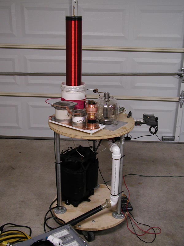
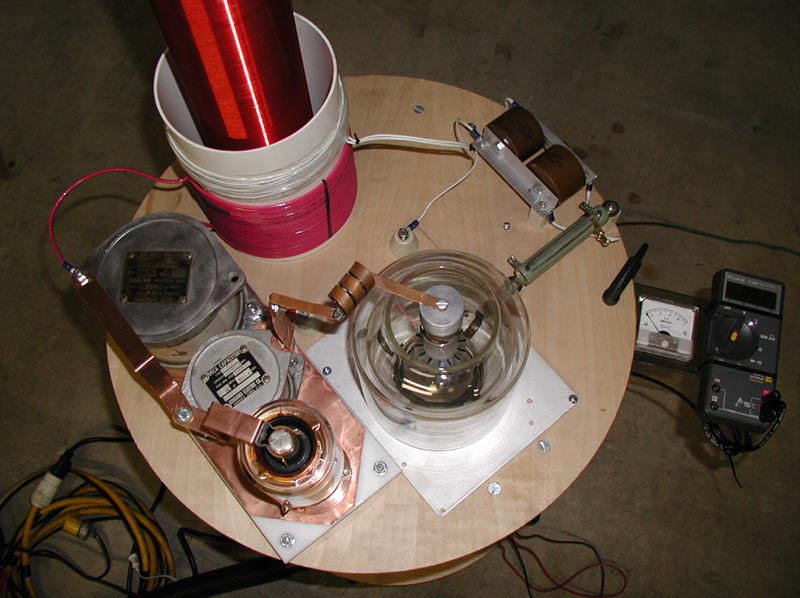
  • Secondary  4" OD plexi, 0.021" magnet wire,  23 5/16" of windings, 
    measured w/ Wavetek 27XT: R=18.5 ohms, L (measured) =18.34 mH, L(Wheeler)=19.6 mH, F(r) Wheeler&Medhurst = 376 kHz
    F(r)= 410 kHz, measured in garage, ~6' to walls, ~4' to ceiling, mounted on stand w/ plate xformer ~1' below,  bare tube socket in place, primary former removed.  F(r) = 404 kHz  with tube, globe, 1 mica tank cap, and vacuum variable cap sitting on top of platform.

  • Primary  6 5/16" SDR PVC, 32T, 12 GA Stranded THHN
    I have 1.27 nF of tank capacitance with the Jennings in the half-way position in parallel with the 2 Mica capacitors.  According to the Wheeler formula, I need about 31.5 turns of L(p) to force the resonant freq of the primary to equal that of the secondary.
    Again,  L was verified by paralleling the primary with a known C and checking F(r). 
    C = 0.57nF, F(r) meas = 550kHz, therefore L = 147 uH, L (Wheeler) = 145 uH.

    Coupling Test on the 32T primary and existing secondary.  I (primary) = 6.83 A, V (secondary) = 1.11 V, therefore K =0.263. 
     Note: I couldn't find the recommended 1uF capacitor recommended in the coupling procedure so I used a 0.1uF instead.

    ---Original Primary design (25T) is shown in green txt---
    6 5/16" SDR PVC, 25T, 12 GA Stranded THHN, 3 7/16" across 24T
    L is was low to be measured with my meter so I added a known capacitance in parallel and measured the resonant freq.  ( Wheeler formula estimates 102 uH )
    0.57 nF = 654 kHz, therefore L(p) = 104 uH
    2.36 nF = 328 kHz, therefore L(p) = 100 uH    << this means that I can trust Wheeler formula for L(p) >>

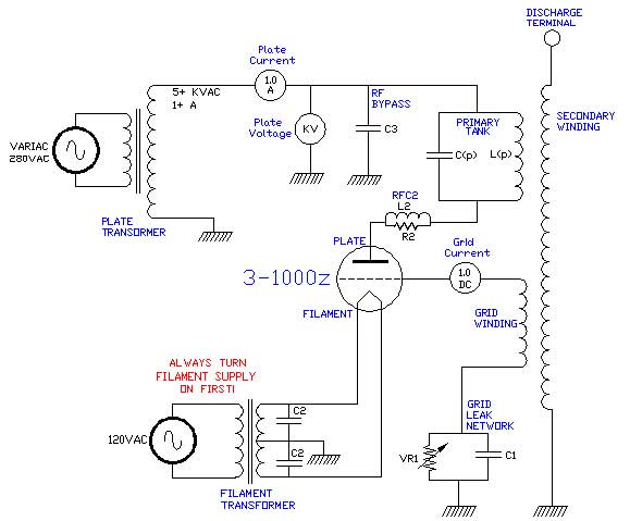
  • Grid Winding  10T + 8T, 16 GA PVC, about 1.25" across windings
    R1 advice from Simon Winder.  " I recommend putting a 50 ohm 3W carbon fim resistor in series with the grid, soldered as close as possible to the grid terminal. This helps reduce parasitic oscillations because it acts as a low pass filter with the tube grid capacitance."

  • Grid Leak Network
    VR1:  7.5 Kohm, 100W.  C1:  3.56nF.  I used (2) Sprauge 2500MMFD, 30KV, 399A259 doorknob caps so I expected about 5 nF.  I checked the battery in the meter and checked the meter against several other caps of a known value and it checks out fine.  Maybe these large doorknobs decrease in capacitance over time or hours of useage???

  • Tank Capacitors  C(p) - used 3 capacitors in parallel
    - Jennings Vacuum Variable Type UCS, 10KV, Number on base is N16-C-65869-204,  measures 0 - 0.450 nF
    - Sangamo Mica, 0.57 nF, 10 KV
    - Sangamo Mica, 0.50 nF, 20 KV 

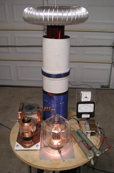
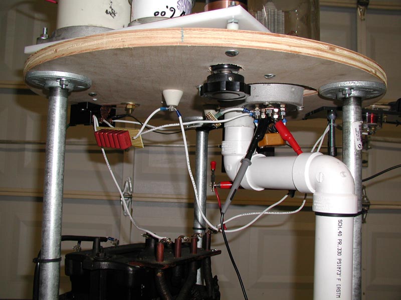
  • Filament Suppy and RF protection
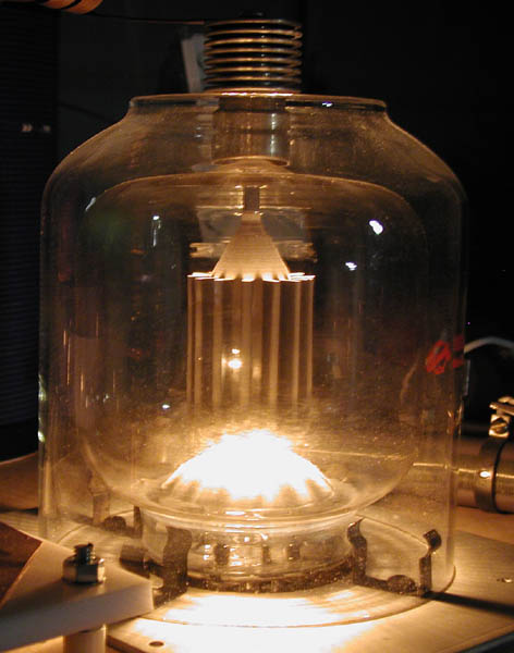
    The filament will be heated with the original 7.5V, 22A filament transformer.  I am straying from typical amplifier design in that I'm choosing not to ground the center tap and I will ground one side of the transformer instead.  The center tap is grounded in RF amplifers to limit "hum" modulation.  I don't have to worry about hum and can significantly reduce component count by grounding one side of the transformer.  RFC1 and C1 are most likely not needed, but I included them in the circuit since they were on hand.  C1 = Sangamo 0.033 MFD, 1200VDCW, 2500VDC test, Mica capacitor.  RFC1 is about 12T of ~10ga magnet wire bifilar wound on a 6" long by 1/2" diameter ferrite rod.

  • RF Bypass between tank and Plate PSU
    C3:  MMC design.  About 10nF of series/parallel metalized PP capacitors of the same type I used in my disruptive tesla coil MMC.  See my MMC page.  

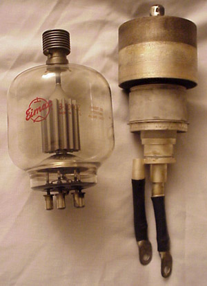
  • RF Choke on the plate
    The following was copied from page 13.25 of the 1998 ARRL Handbook.  "Nearly all vacuum-tube amplifiers designed for operation in the 1.8 to 27.9 MHz freq range tend to oscillate somewhere in the VHF-UHF range - generally between 75 and 250 MHz depending on the type and size of the tube....Stray inductance between the tube plate and output tuning capacitor forms a high-Q resonant circuit with the tube's C(out)"  The article goes on to show schematics and formulas to help understand how the high freq oscillations come about.  It suggests that tubes such and 3-500z may require around 3-5 turns of #10 wire wound 0.25-0.50" in diameter and about 0.5-1.0 inches long.  It suggest that the parallel resistance be about 50 ohms at 2 watts.  Luckily, I saved the choke that the original amplifier builder used

7/30/00

I measured my secondary resonant freq to be about 400 Khz today (7/30/00).
The Excel sheet estimates the unloaded freq to be about 376 kHz.  I need to double check the measurement...


7/13/00.  

Parts are gathered.  I have decided to get the coil up and running on AC and then refine it to run on DC.

all pics on left are "clickable"


3-1000Z    Power Triode            ( The following was copied from here: http://hereford.ampr.org/cgi-bin/tube )

Characteristics

Heater or Filament Voltage . 7.5 volts
Heater or Filament Current . 21.3 amperes
EIA Base . . . . . . . . . . F3
Prefered Substitutes . . . . None
Substitutes. . . . . . . . . None
Capacitances and Design Maximum Values

Cin . . . . . . . . . . . . 17 pf
Cout . . . . . . . . . . . . 0.12 pf
Cgp . . . . . . . . . . . . 6.9 pf
Plate Dissipation . . . . . 1000 watts
Maximum Plate Voltage . . . 3000 volts
Maximum Plate Current . . . 800 ma.
Full Frequency . . . . . . . 110 MHz

Typical Operation as a Transmitting Tube
Class of Service     Vp     Vg     Ip     Ipmax     Ig     Drive     Zl     PO
                GGB     3000     0     180     670     300     65       -     1360

A pdf of the original EIMAC datasheet was found at http://frank.nostalgiaair.orgI put a local copy here for convenience.


Introduction:
I acquired a couple of old tube driven RF Amplifiers that were designed for HAM use.  I found them at a "swap meet" from a junk dealer that apparently was cleaning out the estate of an old Silent Key.  I think the call listed on the racks was K1AY.  One of the amplifiers contains a 3-1000z and the other contains a large ceramic tube, possibly a 3CX1500.  I also obtained the high voltage power supply to drive the tubes.  

tubes2.JPG (36564 bytes)
3-1000Z and an Unknown Tube Bottom view of the RF Amplifiers before I took 'em all apart

Research:
There doesn't seem to be much on the web about VTTC design.   I think this stems from the fact that it's hard to make a canned design for VTTCs since  tubes vary so widely.  Anyway, here are a few sites with VTTC information.  


[ Main Tesla Page | Mail Ross-O]