For all those people who like facts and figures, here are the electrical / physical specs for my coil:
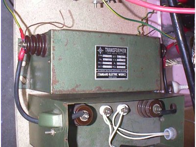
2 x 15kV/30mA (450VA) NST, made by Standard Electric Works (Thanks for the first one, John!)
Note the safety gaps at the top of the picture, bent up out of thick copper wire and set at about 5-6mm from the NST case (which is earthed to RF ground)
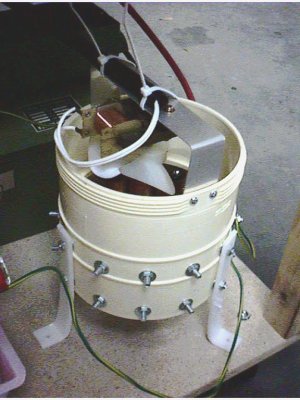
Originally: RQ/TCBOR style cylindrical multiple series static gap:
Eleven 1 1/4" diameter x 3" hard drawn copper pipe segments, 0.028" spacing per gap, each mounted with epoxy and two 1/4" machine bolts to inner wall of 6" OD PVC pipe segment with microwave oven fan for cooling
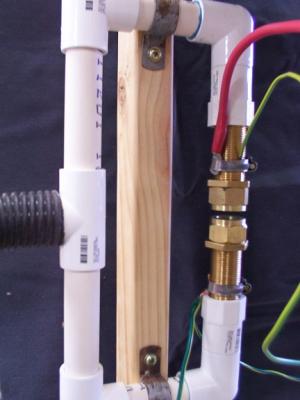
Now: Single static vacuum gap:
Constructed from various 20mm PVC fittings and two lengths of 20mm brass all-thread (plus two brass reducers for the electrode faces). Suction is provided by a 900W portable Hoover vacuum cleaner connected to the gap with a length of flexible hose. Gap spacing is 1/4".
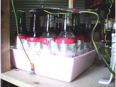
Originally: Saltwater bottle capacitor using sixteen 375mL beer bottles wrapped in foil, 1/2" of 20W50 motor oil floated on top of saltwater in each bottle to act as a corona suppressant
Buss connections made by attaching eight vertical 18AWG lengths of bare copper wire to sheet of cardboard covered with aluminium foil, other connection made by sitting bottles on a sheet of aluminium foil taped to the bottom of the plastic tray the bottles were sitting in
Total capacitance is about 0.012uF (resonant size for 15/60 NST)
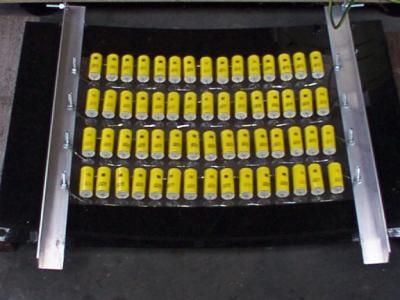
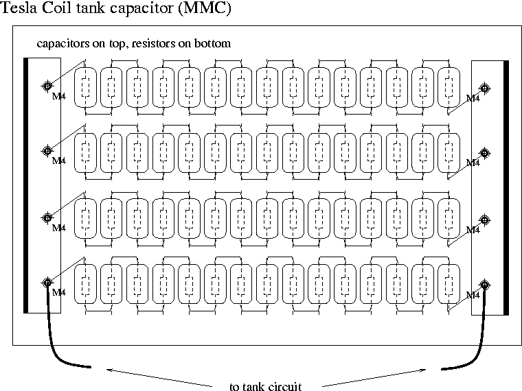
Now: 0.012uF 22.5kVDC MMC using 4 x 15 strings of Arcotronics (RS) 0.047uF 1500VDC polypropylene capacitors mounted on an old microwave door.
Metal glazed 10M 1/2W bleeder resistors across each individual capacitor to remove residual charge after operation.
Streamer length has approximately doubled to 24" just by replacing the SWC with an MMC.
Click on the thumbnail below to see a diagram of my MMC:
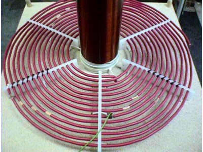
Flat spiral primary level with first turn of secondary, fourteen turns of ~5AWG copper wire, turn-turn spacing is ~3/8", clearance from first turn of secondary is ~1 1/4"
Six primary supports were arranged radially around the secondary by cable-tying them to the wooden platform… these were cut out of a HDPE cutting board and drilled to accept the 5AWG cable. Possibly the most time-consuming part of building the coil was threading the primary wire onto the supports :-)
Currently tapped at 8 turns
Lp = 23.02 uH
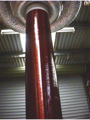
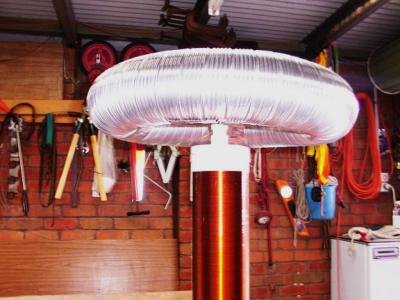
Secondary is 4.25" OD PVC drain pipe wound for 20" (total pipe length was 23") with 22AWG magnet wire, in total about 750 turns. Two PVC end caps were drilled to accept 1/4" machine bolts, nuts, and washers and were press-fitted to each end. These were supported by a saw horses to act as a winding jig. Later, one of these end caps (without the bolt) was used to seal the topload end of the form, whilst the other was cable-tied to the wooden platform so that the secondary could be inserted into it before firing the coil
Winding was sealed with four coats of gloss polyurethane varnish, leaving 24 hours between coats and turning form a quarter turn every 15 minutes or so for three hours after applying each coat
RF ground connection point was made by stripping 1" of enamel from the base lead wire of the secondary and using a strip of aluminium tape to secure it to the base of the secondary. A cable tie was then used to secure a length of 5AWG cable to this connection point. The other end went to a galvanized pipe driven into the ground, which was watered down before firing up the coil
Smaller topload was fabricated from two circular wreath forms (with centre hole punched out) made of florists' foam. These were epoxied together and then sanded to take the sharp edges off and give a more toroidal shape. They were then wrapped with strips of aluminium tape, and a centre disc of cardboard covered with aluminium foil fitted
Larger topload made using 4" corrugated drain pipe bent into shape and wrapped with strips of aluminium foil
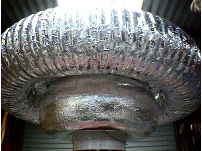
Largest, newest, and current topload made using 4" flexible aluminium ducting formed around two 12" pizza pans pop-rivetted together. Ducting is secured to centre-plate using aluminium tape. I also built a mount for the topload by cementing a 3/4" PVC end cap to the top of the secondary, and also bolting another 3/4" PVC end cap and a solder lug (to which the lead wire on the secondary is soldered) to the underside of the topload. This makes for a secure electrical connection, and also allows me to adjust the height of the topload by using different lengths of 3/4" PVC pipe between the two endcaps (at the moment, I am using a segment of pipe 2" long)
Dimensions of toploads: 4.25" x 10" (smaller), 4" x 19" (larger), 4" x 20" (largest)
Ctop = 20.5 pF
Lsec = 11.7 mH
Cself(Medhurst) = 8.0 pF
Ctotal = 28.5 pF
Fsec(unloaded) = 512.0 kHz
Fsec(loaded) = Fpri = 276.2 kHz
Home | News | What is a Tesla Coil? | Specifications | Results | Links | Tips | Email