Stefan's Tesla-Pages
Technological background, part#3
(or 'how to produce your own indoor lightning')
![[home]](buthome.jpg)

Efficiency of the whole system
(diagrams)
Setup and tuning (tips for beginners)
output voltage
interturn voltage (and breakdown)
Efficiency of the whole
system
The most often heard term in Tesla coiling concerning efficiency is "watts
per foot spark length". But that is not the best thing to describe a system
because of the following reasons:
-
Efficiency in science means "energy in / energy out". But some people
compensate the reactive current with capacitors and measure Watts, others
only VA (which sometimes is double of it!). And how can we measure "energy
out" in Tesla coil systems? The sparks from a Tesla coil are thick or thin,
they are purple or hot-white, there are single-sparks or multiple-sparks.
Some people say that their maximum spark length is the maximum spark length
they ever observed (in countless days of experimentation). Other coilers
take the length of the average sparks or say "25% percent of my sparks are
longer than...". And others again measure the length of so-called attached
streamers which means the length of the longest achievable horizontally arc
which stays permanent.
-
Every system has an other value of losses in the high voltage xfmr
and filter circuit before the tank circuit. So some people say, one
has to take the energy stored in the main cap times the bps as the average
input power.
-
The length of a spark can't be measured correctly in my opinion,
because the endpoint isn't really well defined (the spark will be thinner
and thinner towards its end). So the only real way to measure the length
is to hold your yard-stick to the place where a previous sparc hit anything
and turned to an arc.
-
A nice way to tell what amperage the output sparc (or arc) has, is
to place an ordinary light bulb in the spark path so that the current has
to flow through the filament. You can tell how much amps are involved when
you take a test measurement with another light bulb and your variac. This
way you have also to take skin effect into account. But - this way you can
only measure amperage, not voltage. So there is no way to say how much power
(or energy) is in the discharge.
From the above, you see that the spark length, one can achieve with a given
high voltage xfmr, is not easy to estimate. But it is still the first and
most important question asked by most of the beginners. In the beginning
of my coiling times, I've collected many data points of many different systems
of many coilers (mostly from the Tesla-related email lists, see the
link-section).
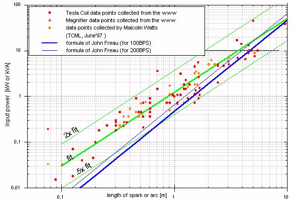
In the first of the following pictures, you can see the traditional way of
measurement: the 'length' (not consistently measured!) of an output
spark or arc is compared with the input power of the whole system ('wallplug
power'). But nobody knows if this will be the real power (measured in WATTS)
or if there is a significant reactive part (VOLT-AMPERES) also in some cases.
This is a very inaccurate comparison, but gives a rule of thumb what one
can expect from a certain xfmr. Most of the data points are within a small
band of factor 2 (half time up to two times) from the 'fit' line.
(Click on the image for a better resolution.)
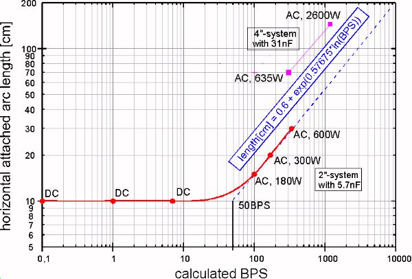
As said, the length of the arcs and sparks is dependent on the brake rate.
To get some information on this important parameter in coiling (think of
rotary spark gaps), I performed some tests with my 2"-system. The cap value
was 5.7nF, all data points were achieved with the same configuration (tuning).
For low breakrates, I used my new HVDC-source (my second
fly back circuit). This source has no centertap of course, so I disconnected
the centertap connections from the filter circuit. The ground connection
of the source was connected to the safety ground, and to the RF ground on
the other side of the filter circuit. The thin spark was not very bright
and only barely visible, so I decided to measure the length in 'horizontally
attached arc length mode' to get the max. length each arc achieved.
Surprisingly, at frequencies up to about 7Hz, no dependence of the BPS was
detectable. When I switched to my 10kVAC-source (with centertap), the first
'smooth' run when turning the knob on the variac indicates probably 100BPS
(at 180W input power, the 'matched' value). When I turned the variac further
up, the break rate rised (at least theoretically - I had no scope available
at this time to verify this). I got the following diagram, where I added
the measurements with my 4"-system done in August '97.
The last picture shows the relation between the applied voltage (line
frequency), radius of curvature and the distance between the electrodes
(data from several different books as well as own measurements). As said,
this picture is for line frequency (50Hz), our Tesla coils work from 50kHz
up to 5MHz! So please don't apply this data to your coil, because high frequency
Tesla discharges can jump several times this distances, depending on many
other factors (bps etc.). I placed this diagram here because it shows the
relation between the radius of curvature and the voltage. (Click on the image
for a better resolution.)

It is very difficult to measure the output voltage of a Tesla coil directly.
There is an interesting thread on the TSSP and TCML mailing list in late
summer 2004.which will perhaps clarify something in the near future.
From the point of energy, there can be no more energy in the total capacitance
of the secondary than previously had been in the primary cap. This equation
gives an upper limit for the maximum voltage Ûsek produced
by a certain coil. A bigger toroid leads to less voltage but more (pulse)
current available. Experience has shown, that in most cases a bigger toroid
means fatter and longer sparks because the spark grows also through
current. So a 'cool' coil is perhaps not always the coil with the highest
output voltage. Look at the section below on this page for
calculating the maximum output voltage.
back to the top
Setup and tuning
(general tips for beginners)
-
When you set your system up for firing please be aware of the following things
(read this section completely before applying power!):
-
-
-
Unplug every sensitive electronic equipment in your house (and remove the
cables from the devices if possible - at least coil them up so that no high
voltage can be induced).
-
Check all connections twice (especially the RF-gnd).
-
Don't through everything together, make a 'clean' setup instead and fix the
components so they can't fall from the table!
-
The toroid usually is not fixed, so be carefull that it can't fall down when
the TC is operating (important when you coil in the garden and the wind is
blowing...).
-
Place the primary coil about one primary coil diameter above the ground or
heavy eddy currents will be generated in the well conducting concrete garage
floor (robbing you power).
-
Don't try this at night because you want to see where the high voltage leads
are (and the neighbours want to sleep...)
-
Tuning means to bring the secondary coil (with its top load) in resonance
with the tank circuit. Under the assumption that our calculations are
not to bad, one should achieve resonance by finding the right tap point on
the primary coil (if not, one has to change the top capacitance of the secondary
or the capacitance of the tank circuit). This is usually done by tapping
at the expected point minus one turn (this is for stray inductance in the
tank circuit wiring). The following section is mainly based on a text from
Mike Hammer I found in my early coiling days somwhere in the web, spiced
with my own experience:
-
-
-
Again: BEFORE throwing the main switch, READ THE SAFETY PAGES OF AS MANY
COILERS AS YOU CAN!! (Or at least mine and the one on the TCML)
-
Have someone else with you (if something goes wrong) and the fire extinguisher...
-
AND UNDER NO CIRCUMSTANCES TOUCH ANY COMPONENT WHILE THE SYSTEM IS PLUGGED
IN!!!
-
wear hearing protection above1kVA indoors (and safety glasses if you have
salt water caps with glass bottles).
-
Be sure not to tune to a harmonic of the frequency of the secondary such
as 3/4 lambda or 5/4 lambda.
This will destroy the secondary in the moment you apply full power.
-
To be sure, you can measure the frequency of the primary circuit and
the secondary:
Primary: disconnect your xfmr and short out the spark gap. Feed the
primary coil (which is then in parallel to the primary capacitor) via
a resistor of sufficient resistance for the frequency generator (don't overload
the f-gen's output, this will give false readings!) with the f-gen (hot and
gnd to both ends of the primary coil). Connect the o'scope in parallel to
the circuit (which means also across the primary coil) and look for voltage
rise at resonance.
Secondary: Connect the bottom of the secondary via a 1-10kOhm-resistor
(don't overload the f-gen!) to the hot output of your f-gen and look for
the voltage rise across the resistor which will occure at resonance due to
the increased current the secondary will draw.
-
Check the safety gaps again (with disconnected tank circuit of course).
-
Double check all of your connections. Run your grounds and double check those.
Never take any connection for granted. Set the secondary into the primary
and attach the RF ground.
-
Pin a long nail (at least a thumbtack) onto the toriod to give the arc a
starting point (you can also bring a ground wire near to this nail). Sparks
will easily break out from such a point.
-
Next, CLOSE YOUR MAIN SYSTEM SPARK GAP DOWN!!! (Decrease the number
of gaps.) I can't overemphasize this point. Don't run a lot of gap. This
will limit the peak voltages in the primary to low levels while things are
out of tune. As things are brought closer to resonance the gap can be opened
a little at a time to increase the primary energy level.
-
Don't throw full power into a new coil or a newly rearranged system. If you
do, you may damage components. The coil must be brought into tune and up
to full power gradually. The use of a variac is highly recommended for
controlling the input voltage to whatever step up transformer you may be
using. Never throw full power to a coil until you are sure the system is
in proper tune.
-
Test with low coupling (secondary raised some cm).
-
Apply a bit of power until the spark gap fires.
-
If no spark breakout is seen from the discharge terminal don't worry. Use
a flourescent bulb as an indicator layed on the toroid (don't hold it in
your hand!!!). As the coil gets closer to resonance the farther away and
brighter the bulb will glow. Turn off the coil and move the tap connection
on the primary coil a half turn and check the bulb brightness. Then move
it a full turn in the opposite direction and note the brightness of the bulb
again. This way you can determine the direction the tap needs to be moved
to locate the proper tune. Open the main and safety gaps up in steps. Apply
the same voltage input (low power) and check for discharge. Once spark has
begun to break out of the discharge terminal use it as a visual indicator
of tune.
-
Increase coupling (lower the secondary) slightly.
-
Tune for best spark (move tap on the primary coil).
-
Repeat until lowering the secondary again will produce less spark length.
-
Then raise your toroid some cm.
-
Retune for best spark (move tap on the primary coil).
-
Raise your toroid some cm again.
-
Tune for best spark (move tap on the primary coil).
-
Repeat until spark length is maximum.
-
If you find the best tune point is with very few primary turns then your
primary cap is too large. Adding a larger toroid to your secondary will lower
its resonant frequency and allow you to tap in more primary turns also. If
you get tuned all the way out to your last primary turn and you still haven't
found the resonant point, then your primary cap may be too small or your
toroid too large.
-
-
A system in proper tune should not break down the safety gap often. The safety
gap once set properly should not be too active.
-
-
If your safety gap is firing continuously then you may be out of tune or
you may be running too wide a main gap. Try closing down your main gap slightly
and retuning for best output.
-
-
The only thing I would like to add to that is you should always work towards
having as many primary turns tapped in as possible. Higher primary inductances
improve gap operation. One thing you can do to allow for more primary turns
include adding a larger toroid to the secondary. This will give several benefits.
The lower resonant frequency will allow for more primary turns and the larger
capacitance represented by the toroid will give longer hotter sparks. Plus
lower frequencies give longer sparks due to the lowering of several loss
factors like corona loss and loss due to skin effect.
-
-
Last safety hint:
Ozone is classified as a health hazard at quite low concentrations. If you
can smell it, the concentration is already well above safe limits. The smell
is a slightly sweet bleach type odor. You may also notice some stronger biting
odors. These are caused by various oxides of nitrogen. These are even more
noxious than ozone. These gases are produced in great quantity by our spark
gap and secondary output. They are a fact of life with high voltage and should
be dealt with. Provide some form of airflow to the outside if you coil indoors.
Open a window for fresh air. If all else fails limit run times and remove
yourself to fresher air.
back to the top
-
How to calculate the output voltage?
My way to do this is via energy preservation. But this of course only gives
a maximum value.
-
-
The formula is:
-
| Eprim * (1-loss) = (Eself + Etop) |
|
|
|
| (1-loss)*[ 1/2 *
Cp * Ûp2 ] =
[( Eself ) +
(1/2 * Ctop *
Ûtop2 )] |
|
|
(1) |
-
If I remember right, Terry says that about 1/4th (loss=0.25)
of the energy you pump into the system will not make its way to the secondary,
I have to verify this or at least have to find his posting on the TCML again.
Until then, I will write this as a variable factor.
-
Problem is how much energy (Eself) will be stored (='lost') in
the selfcapacitance of the coil. To calculate this, we have to take into
account the nonlinear voltage rise along the coil length and the nonlinear
selfcapacitance along the coil length (and perhaps a phase angle?).
-
I think the worst case is an effective self capacitance (as calculated via
the Medhurst formula) and a linear voltage distribution (which seems to be
a good approximation for coils with a not to small toroid, Terry performed
some
measurements
on this for the TSSP, see also the exact math on the TSSP website), so we
can say that the maximum energy 'lost' in the self capacitance is:
-
| Eself = 1/2 * Cself *
(Ûtop/2)2 |
|
|
(2) |
-
When we combine formula (1) and (2), we get
-
| (1-loss) *
[1/2*Cp*Ûp2
] = [
1/2*Cself*(Ûtop/2)2
] +
[1/2*Ctop*Ûtop2
] |
-
-
and therefore
-
| (1-loss) * Cp * Ûp2 =
[
(1/4*Cself +
Ctop) *
Ûtop2 ] |
-
which gives finally
-
| Ûtop = Ûp * sqrt
{[ Cp * (1-loss)
] /
(1/4*Cself +
Ctop)
} |
|
|
|
(3) |
-
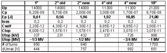
-
(have to check if the data used for 2"new, 4"new and
10" is still valid)
-
-
back to the top
-
-
I guess the major problem is a short between
two secondary windings approx. 1/3rd up of the lower end of the coil (as
happened to a coiling friend twice when I visited him). The voltage rise
is a bit higher here (lets call the factor "a" here, it depends on the size
of the toroid, in Terry's measurements it is about 1.12) because of the slightly
nonlinear voltage distribution along the coil.
-
-
This would give you a voltage between two turns of
-
-
where N ist the total number of turns.
-
-
From my memory (which is degrading from day to day :'-( ) I
would say that most wires in the 0.5-2mm range are rated 2-3kV (single enameled,
up to 7kV for triple enameled). As you have two insulations between two turns,
the insulation should be good for at least 4kV interturn voltage. But better
check the insulation via its data sheet or an destructive test (shunted xfmr,
variac, two twisted wires) and derate by factor 3 for RF (your test will
be only 50Hz!) and factor 1.5 for safety reasons (totally factor ~4). Perhaps
you can perform the test with RF in a small tank circuit, that would give
more reliable results. The rough estimation gives a permissable dÛmax
of approx. 1kV, so I'm right in the ballpark with my coils.
-
-
back to the top
-

-