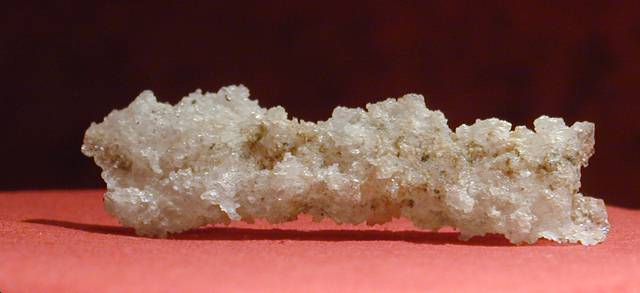
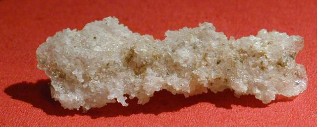
Some more photographs of my beautiful fulgurites
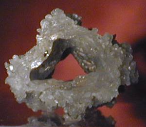
The original one made by lightning
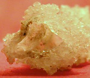
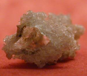
The ones made by Toni and me (and also Daniel and Max)
| a look into the tube: |
|
|
from the side: |
 |
 |
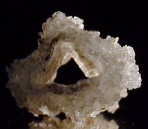
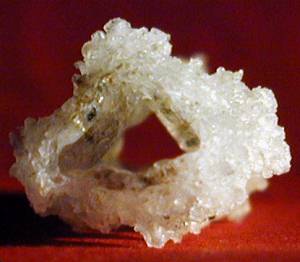
some views through the tube: |
|
 |
 |
more views through the tube: |
|
 |
 |
| see how transparent it is: | |
 |
 |
On Halloween 2005, my fellow coiler Toni and I made some Fulgurites using his BIG 10kV (at 50kVA!) xfmr. I found some information on how to do this on the website of GTL-member Stefan Binder (http://stefanbinder.privat.t-online.de/fulgurites.htm) and at the 4HV-forum (http://forum.4hv.org/index.php?board=4;action=display;threadid=4165).
So we connected two phases to 400V over a 7.25Ohm resistor (breaking resistor of a crane, thanks again to Stefan Bauer for donating this beast to me!). A measurement before with 230V applied to the high voltage side of the xfmr resulted in 6.9V on the low voltage side, so the transformation ratio is approx. 1:33.
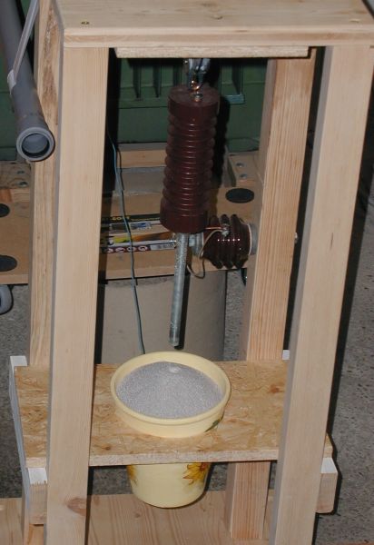
We filled a flowerpot with silica sand. One electrode of the xfmr was burried at the bottom of the pot (screwed through the bottom hole) and we sticked a copper pipe (8mm diameter) into the pot before filling in the sand. The copper pipe can be pulled upwards with a lever mechanism while the arc is burning. We measured 28A on the low voltage side (arc current approx. 0.93A) at the beginning down to 20A (0.67A arc current) when the arc broke apart at the end of the pulling process. The slower you pull, the thicker the glass wall will be (=> more sturdy fulgurite). We started with a pulling time of approx. 1min for the first fulgurite up to 2-3mins for the third one.
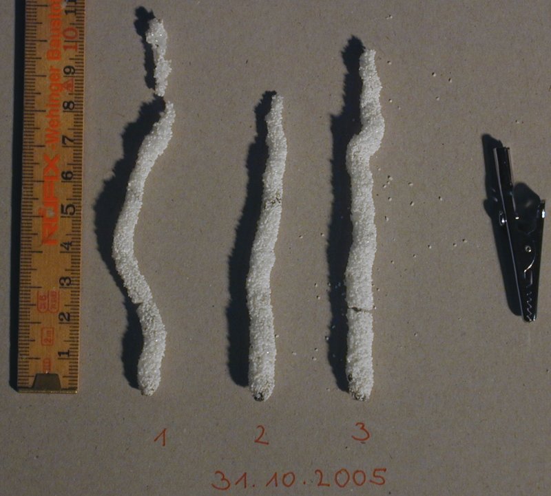
We achieved 3 hollow fulgrites in the first three trials! Length was approx. 10cm (4") with an outer diameter at the lower end of 6-8mm and a wall thickness of 0.7-1mm. The bottom end was fatter (bigger diameter) because of the higher current at the beginning. After a certain length of arc (and fulgurite) was created, the resistance of the arc rised, reducing the current and therefore the arc diameter.
Here you can see Toni at the lever mechanism, the flowerpot on the left at
the floor and the big green xfmr behind the stairs on the left side:

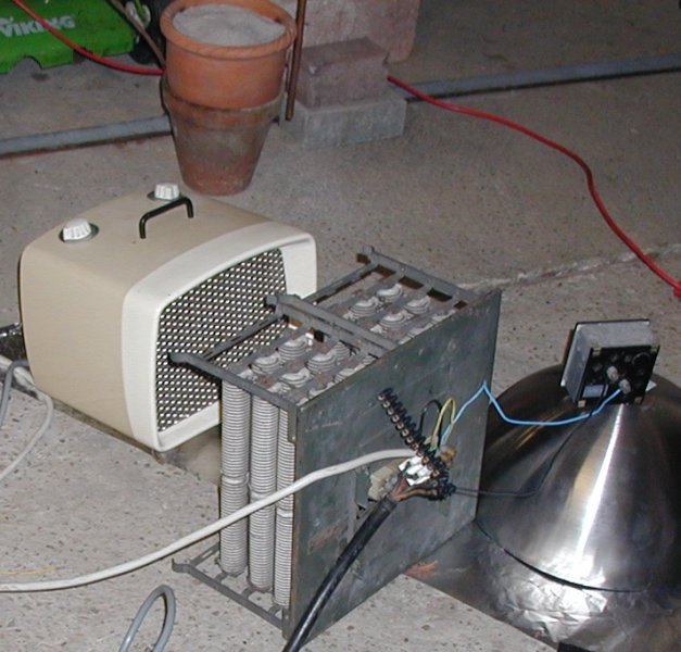
This is the big resistor, we used a blower for cooling (resistor was rated
for 12A at 40% duty ratio, not for the 28A cont. we pumped through it...),
on top of the IKEA salad bowl is the ammeter:
Our first homemade fulgurites:
A view inside:
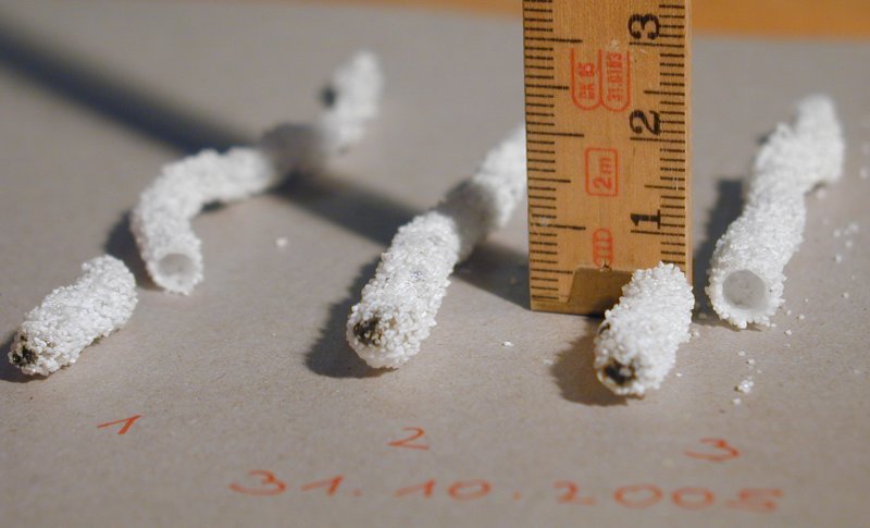
A closer look:

At first, I wanted to create fulgurites the original way with a pulse discharge. But lets see how much energy we needed to produce the ones (100mm x 4mm average diameter) seen above: we wasted some voltage in the resistor: dU=R*I = 7,25*25=181V, so the xfmr got only 212V at 25A for 120s, that's 636kJ! (Yes, I know this is not really the right way to calculate this, but it is sufficient for a rough calculation I think.) Compare this to the really big capacitor bank I plan together with Daniel and Toni at the moment which will have "only" 47kJ... With this capacitor bank, we perhaps can produce a 2cm long fulgurite of 2mm diameter (1/10 of the volume of molten silica sand of the 10cm-fulgurite pictured above). The geometry of this smaller fulgurite will be not so impressive but the process of creation will be for sure! Perhaps we can do this at one of the the Teslathons in 2006+x...
Plans for the next session:
We plan to use inductive ballast instead of resistive elements (inductor
made from "FhG-xfmr", core area per leg: A=9cm x 5,6cm = 50.4cm²):
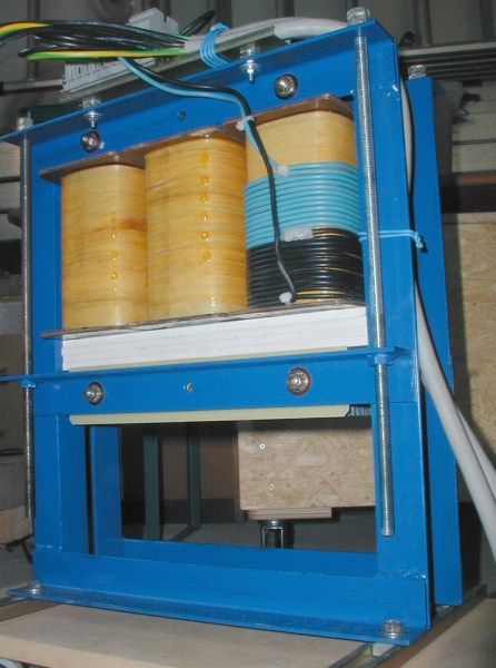
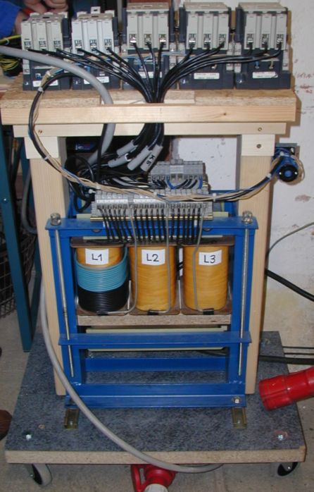
We want to adjust the ballast during the pulling process to get a fulgurite with a more even diameter (motorized inductive ballast, mechanism still to be buildt).
We'll insert an Ampere-meter (~2-5A) on the HV-side of the xfmr to monitor the arc current. If the arc curent drops suddenly, the pulling process is to fast so we'll have to slow down.
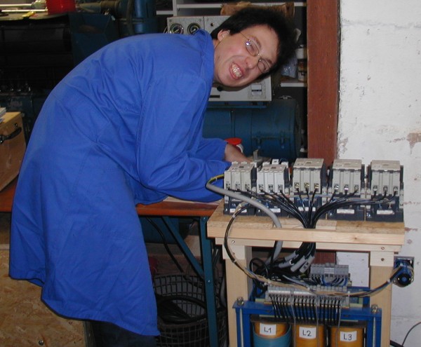
The xfmr should be connected to 3 phases on the low voltage side to pump
even more power through the arc to get fulgurites with a bigger diameter.
(3ph 35A each instead of 2ph 28A). Since the xfmer is connected in Yz5, all
the three inputs will deliver some current to the two output terminals we
use. We will feed u,v,w and pull the arc between U and W. To maximize the
output current, the switch should be connected to position 3.

Additionally, we'll use 3 Ampere-meters, 1 Volt-meter, 1 Watt-meter
and perhaps also a cosPhi-meter on the line side.
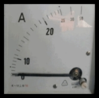

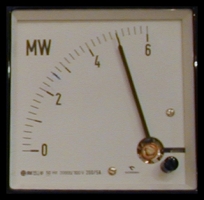
We still have to change the scale on the wattmeter, it is factor 200 wrong
;-)
Adding of compensation capacitors to the low voltage side of the xfmr should
boost the output current while still feeding it from 3ph 35A each. For that
purpose, we made a giant 3x 266µF capacitor bank rated for 400+V:
If that should not be sufficient, I have 3pcs, 220uF rated for 230Vac (that's
ok since we connect the caps in star (Y) not delta configuration) an 25pcs.
40uF rated 230V too.
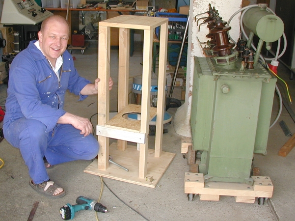
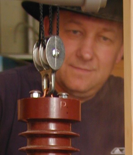
We want to build an automated mechanism for pulling more even and much more
slowly (motorized by a linear motor). At the moment, it is just a lifting
block without the motor:

Another idea was to use a very small diameter copper wire instead of the copper tube. The arc will be established at the lower end of the wire and will slowly melt upwards due to the heat of the arc. With this mechanism, an automatic finetuning of the fulgurite diameter might take place because when the arc (fulgurite) is longer at the end of the pulling process, the time for melting another length of copper wire will be longer when the arc burns cooler. But replacing the thick diameter electrode against a small diameter copper wire might give us no hollow fulgurites anymore.
On 6th August 2006 the Teslathon2006 organisation team (Toni, Daniel, Max and me) hold a workshop at Tonis house to discuss the last Teslathon. Toni couldn't attend the Teslathon2006, so we performed a small one the day after where we electrified the glass plate (34cm arcs around the edges).
We also drew some more fulgurites:
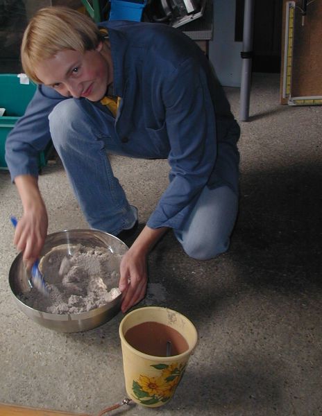
Max is filling in the sand:
Ok Dr. Mabuse, give us some power!

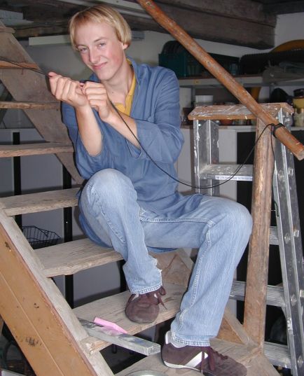
Hey Toni, it works! Max is pulling the string.
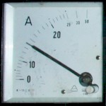
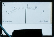
A look at the instruments during the process (@ 3 phase 400V without
compensation caps):
I(L1)=14A / I(L2)=28A / I(L3)=15A / P=2.1kW (full scale is 33kW instead of
6MW) / Isec=0.9A
(from left to right)

The reactive power was approx. 2.1kW during the pulling process, the used
energy therefore approx. 1.2MJ or 0.35kWh (that's 27 times the 47kJ of the
capacitor bank, Daniel, Toni and I plan top build together!).
Thanks to the increased pulling time (nearly 10 minutes), our new fulgurite
in standard form (slightly bended hollow tube) reached a new record size
of 19cm length and 18mm outer diameter:

I'll try to cut it open to get a view inside during the next view
weeks...![]()
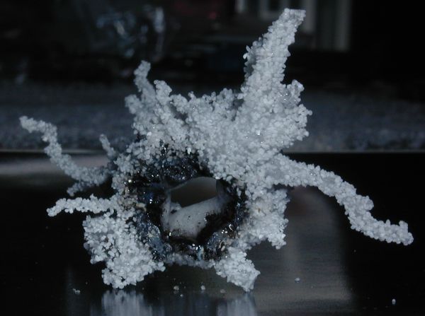
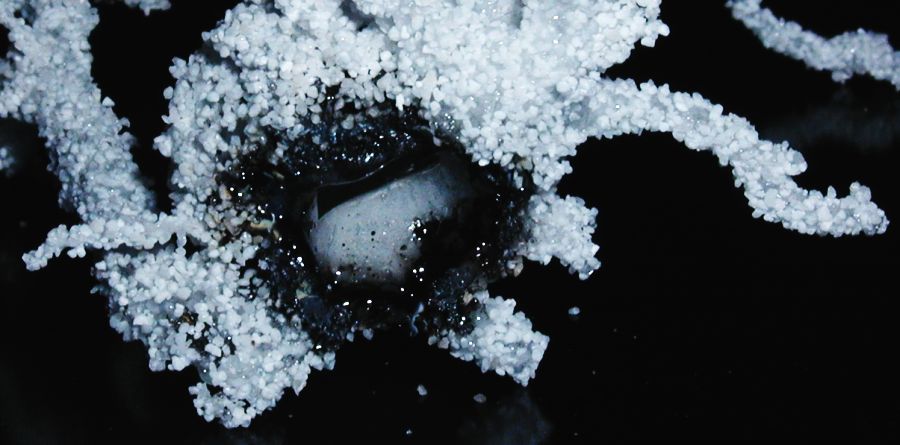
We even developed a new process for creating branched
fulgurites! To our knowledge, that was the first time,
artificial fulgurites with multiple branching could be produced.
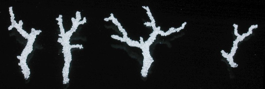
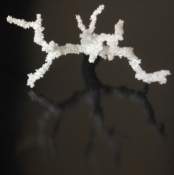

Most of theses fulgurites had a length of ~5cm and were therefore significantly
smaller than the straight ones. Additionally, the branched ones were massive
as opposed to the straight hollow ones. Our next goals are to make the branched
ones now bigger, hollow and more colorful.

< more images coming soon
>![]()
An interesting scientific paper on how to make a fulgurite using natural
lightning:
http://plaza.ufl.edu/rakov/Gas.html
And yes, we still have some good ideas how to make some more special things
out of molten sand ;-)
(See my email 10.08.2006)
Some interesting links to fulgurites:
http://www.lightning.ece.ufl.edu/general.html#top (papers)
http://www.ece.ufl.edu/labs/melemag.html (Bild)
http://home.att.net/~allanmcnyc/molesworth.html (manmade fulgurites)
http://www.lightning.ece.ufl.edu/
http://www.ece.ufl.edu/profiles/pfelma.html#umamar
http://www.weatherwise.org/98ja.wright.html
http://www.usatoday.com/weather/wlightn0.htm
http://www.highvoltagephotography.com/index.html
das andere "triggered lightning lab" (langmuir, new mexico): http://bat.nmt.edu/
http://home.att.net/~allanmcnyc/molesworth.html
http://home.att.net/~amcnet/sidebar.html
