My 4"-System
description of the parts and pictures of the photo session in August '97 and some new thoughts
Specs of the 4"-system in August 1997:
Results:
To make it short, after some days of experimentation, I ended up again with
space problems, because the produced arcs exceeded the length of 56" (1.43m).
The typical spark length (length of most of the sparks) was around
31/2 feet. Now I know that my 4"-system can produce
arcs longer than 41/2 feet, but I have no chance to
measure them :-( .This makes me even more sad as I recently found
six 50mA@8kV-neons for free which makes it possible to use all of the power
the line gives me at 230V (16A cont. or up to 30A for short time runs). Well,
this should be the goal during the next years as well as finding a place
to fire those bigger and bigger TCs up (until I eventually decide to make
a 15kW DC-TC with all 3 phases of the line... ;-)
But perhaps I switch to magnifiers some day and use the power more efficient. I made my first 3-coil-system also during the August'97 experimentations, but it was not a real magnifier because it only consists of what I had at hand: two secondaries at the right frequency, but not a tight coupling primary, a high current secondary, a short tertiary or a really fast quenching gap. So the result was as expected, the sparks were of the same length as they were in the system where I used the 2"-secondary originally. But it was my first 3-coil system :-)!
Another personal record I made during these days was 28" (70cm) arcs with
only 635W (?? have to measure this again with 30nF,
this is the value for 9nF) input power to
my 4"-system. This was done with all of my caps (around
30nF at this time) and lead to "resonant charging". Lets do some math here
to explain this: Power from one xfmr is 635W at 8kV. So the current
is 80mA. The impedance Zx of the xfmr is therefore
8000V/0.08A=100kOhms. For resonant charging,
the impedance of the cap
(Zc=1/2.Pi.C)
must be equal to the impedance of the xfmr. So the right value of the cap
would be
C=1/2.Pi.Zx=32nF.
This resonance condition leads to a rise in the voltage. I observed this
by adding more identical xfmrs as I wondered about the voltage where my main
spark gap breaks through (all time with 30nF): one xfmr -> 50V, two xfmrs
-> 100V, three xfmrs -> 150V, four xfmrs -> 200V. So by adding more
xfmrs, the 50Hz resonance circuit comes more and more out of tune. From this
it is obvious that the right capacitance for 4 of these neons would be around
128nF but up to now I have no more caps.
One more thing I played with was a pickup-coil made from my old secondary of the school project and T7 for tuning it. A neon indicator bulb was placed between the coil and T7. I connected the base of the pickup coil directly to the ground rods in the garden. I was able to light the bulb by turning my TC on at the first floor.
Images from the August '97 photo shooting:
All spark lengths are measured straight line point to point!
| Setup: | ||
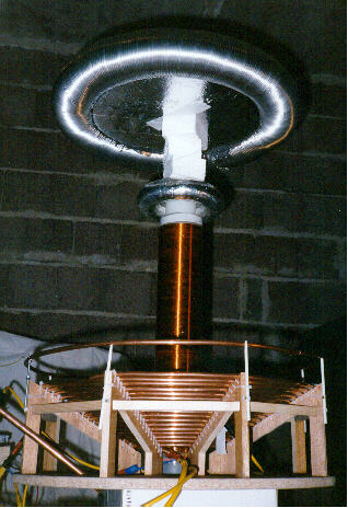
|
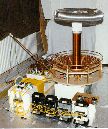
Setup of the session performed with the 4"-secondary in August '97 in the basement of my parents. | |
|
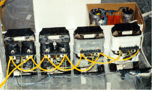
4 Neons 63mA/8kV (driven up to 2600W) with PFC-caps (174µF). | |
|
Filterboard (labeled image) with bypass caps, safety gap, damping
resistors and chokes (click here
to get the unlabeled image).
I don't recommend the use of chokes any longer, better use an RCR-network instead of the chokes! |
|
|
2 of 3 cardboard boxes, each containing 8 salt water caps (1 liter Schweppes bottles) for a total capacitance of around 30nF. Click here to go to my capacitor page. | |
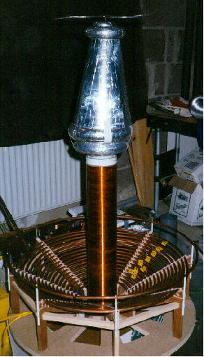
|
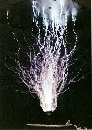
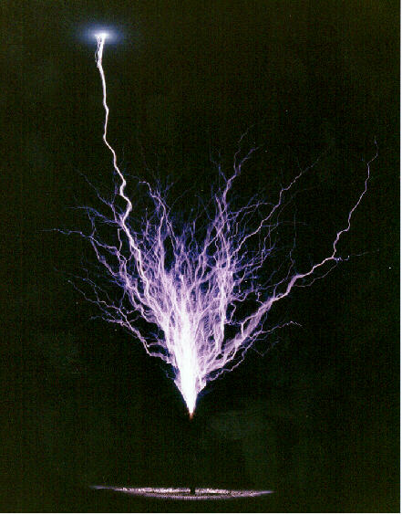
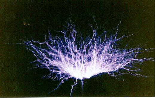
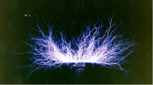
Setup for max. spark length (single sparks from toroid T8). Max. arcs with this 4"-secondary and 2600W input power: 143cm (4'8"). | |
|
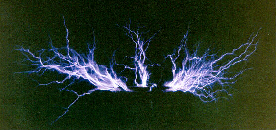
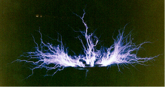
Setup for other beautiful displays, e.g. "ring of fire" and "pinwheel". The T8 was replaced by several other toroids and a conical section. | |
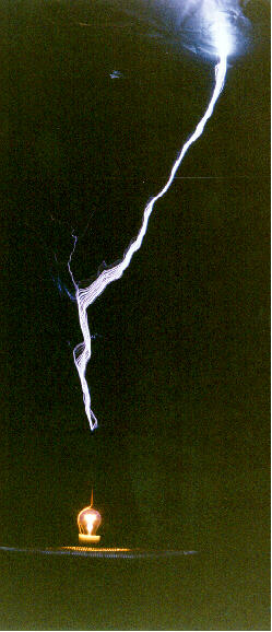
| Plasmaglobes: | |||
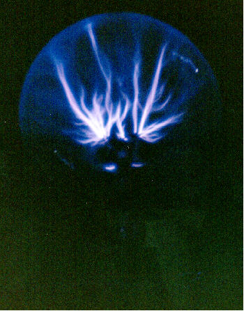
|
Plasmaglobe (12cm = 5" dia) on top of T8 on the spark gap excited TC (systemV1, 2600W), a nearby placed pencil reduced the electrical stress on the globe (and prevented the poor globe from puncturing by the wild 45" long sparks). | 400ASA, f5.6, 1/15s | |
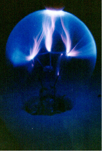
|
Plasmaglobe (6cm dia standard light bulb) driven by a fly-back circuit with two 2N3055. | 400ASA, f5.6, 1/4s | |
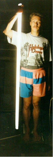
| HV-tricks: | |||
|
This is me standing on the electrode of the fly-back circuit, holding a long fluorescent bulb in my hand. | 200ASA, f5.6, 8s | |
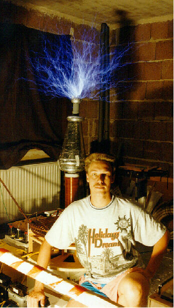
 |
Me and my TC. DO NOT ATTEMPT THIS! This photo is taken by trick photography J. NEVER TOUCH THE PRIMARY OF A RUNNING TC! NEVER GO AS NEAR TO A RUNNING TC! Input power 2600W. Max. spark length from the fast spinning pinwheel is about 57cm (22"). | 200ASA, f3.5, 4s (additional photo taken by light with automatic) | |
|
DO NOT ATTEMPT THIS! This photo is taken by trick photography J. NEVER TOUCH A RUNNING NEON XFMR! NEVER GO AS NEAR TO A RUNNING TC! Input power 2600W. Max. spark length 68cm (27"). | 200ASA, f5.6, 4s (additional photo taken by light with automatic) | |
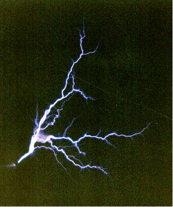
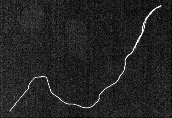
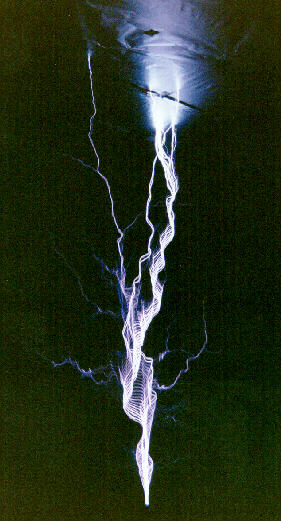
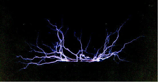
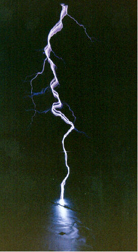
| Lightning bolts (all pictures shown upside down): | |||
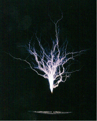
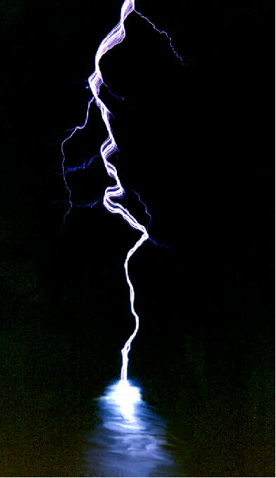
|
115cm (45") long power arc to the ceiling, upside down it looks like a lightning bolt striking into a lake. Input power 2600W. SystemV1. To make the picture look 'more realistic', I removed the TESA-strips from the 'lake'. If you want to see the original photo, click here. | 200ASA, f5.6, 1/8s | |
|
Another 115cm (45") long power arc from the styro ball on top of T8 to the ceiling, upside down it looks again like a lightning bolt striking into a lake. Input power 2600W. SystemV1. | 200ASA, f5.6, 1/15s | |
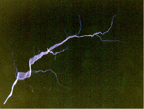
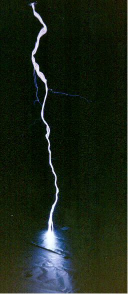
|
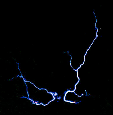
Sparc from T8 (systemV1), upside down it looks like a lightning bolt. Input power 2600W. | 200ASA, f3.5, 1/30s | |
|
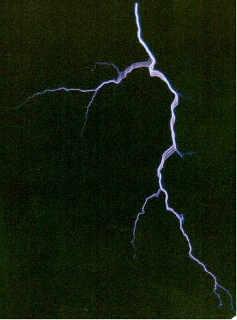
F10B14 "2Bolts" |
Sparks from the styro ball on top of T8 (systemV1) , upside down it looks like two lightning bolts. Input power 2600W (current background picture). | 400ASA, f2.8, 1/60s |
| Flame: | |||
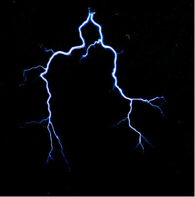
|
F08B11 "Flame2" |
Long time exposure of many sparks, flame like display. SystemV2. Input power 2600W. | 200ASA, f5.6, 4s |
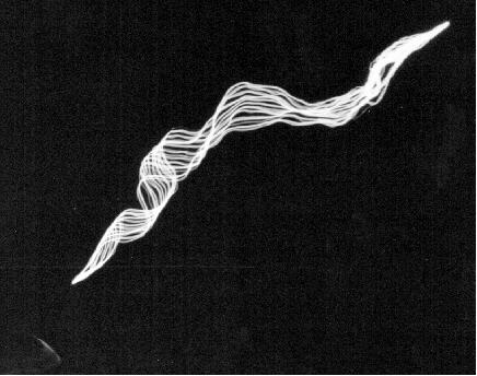
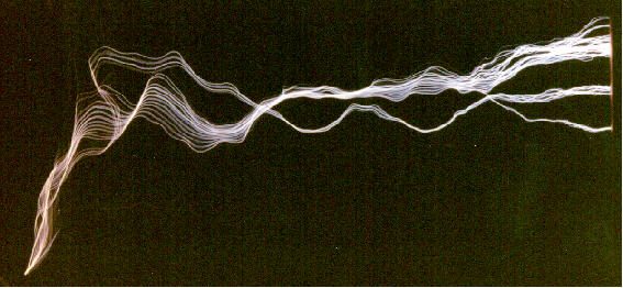
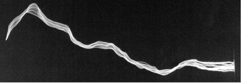
| Pinwheel: | |||
|
Low speed pinwheel, the sparks are twisted due to the movement of the ends. Input power 2600W. | 400ASA, f2.8, 1/60s | |
|
High speed pinwheel, short time exposure, note the red glow of the neon indicator lamps. Input power 2600W. | 200ASA, f5.6, 1/4s | |
|
High speed pinwheel, long time exposure. Input power 2600W. | 200ASA, f8, 4s | |
| see also the trick photography of the pinwheel | |||
E=1/2.C.Û2=.5.30nF.1.4.8000V.1.4.8000V=1.92J.
Some more math around my 4"-system (as configured in 1997):
Cp=30nF

    L=16uH

    f=230kHz

    U=8kV

    Ep=1/2.C.Û2=1.92J=1/2.L.Î2
=> Tank circuit peak current Î=
490A, reactive power per pulse was about U.I= 2.8MVA.Es= up to 0.5 times Ep (no
measurements on the efficiency up to now)
Cs=30pF
Ûs=sqr(2.Ep/Cs)=
up to 253kV.
The sparking secondary rings down in about 5 cycles (guess). From
the light bulb experiment we get
Is=0.16A RMS. So we can calculate an RMS (per pulse) current of
64A for this power arc. Being conservative, the reactive RMS power
per pulse therefore is in the order of 7MVA.
Capacitor:
I got some Maxwell caps for my BIGcoil, so I can use the WIMA caps to build an MMC for my 4"-TC. Further I will build a new primary coil which will take the new cap into consideration. Of course, the secondary will get the new 6"-toroid.
![]() Hopefully,
my 4"-TC can be driven up to 2m spark length (nearly 4 times the winding
length) which equals about 1.85kW input power at 100BPS according to
John Freaus formula
Hopefully,
my 4"-TC can be driven up to 2m spark length (nearly 4 times the winding
length) which equals about 1.85kW input power at 100BPS according to
John Freaus formula
spark length = 5.8 * sqrt (power input) / 4th
root ( BPS)
At 9.4kV (8kV-neons with some additional voltage due to the variac
step up at full scale) and 2000W input power, the resonant value is
72nF. Since all the components neede for this
hobby are really heavy, I'll use no variac if the system is brought roughly
into tune (=>recalculate for 8kV). For a static gap, best size
(LTR) is 120% (160%) of this value which
will result in 87nF. (For an SRSG, 260% (320%)
of resocap size will be best, this will result in 188nF).
I will use two or three 63mA-neons with their shunts removed (the four unmodified neons I used in 1997 didn't get warm even after prolongued use).
Thanks to Kurt and his great EXCEL-Sheet (http://home.datacomm.ch/k.schraner/MMCcalcWIMA33b.xls), I calculated some variants of a suitable MMC out of the WIMA FKP1 (6kVdc, 33nF, 700Vac):
3 caps in series:
| static gap: | 8 strings in parallel | 88nF | 7.8J per bang | 24 caps needed |
| SRSG (100 BPS): | 17 strings in parallel | 187nF | 16.5J per bang | 51 caps needed |
4 caps in series:
| static gap: | 11 strings in parallel | 91nF | 8J per bang | 44 caps needed |
| SRSG (100 BPS): | 23 strings in parallel | 190nF | 16.8J per bang | 92 caps needed |
5 caps in series:
| static gap: | 13 strings in parallel | 86nF | 7.6J per bang | 65 caps needed |
| SRSG (100 BPS): | 28 strings in parallel | 185nF | 16.3J per bang | 140 caps needed |
6 caps in series:
| static gap: | 16 strings in parallel | 88nF | 7.8J per bang | 96caps needed |
| SRSG (100 BPS): | 34strings in parallel | 187nF | 16.5J per bang | 204 caps needed |
So, which one will be realised? Though the experience of others say that 3 caps in series will be sufficient, I will take more to be on the really safe side (so I'll have some margin if anything goes wrong). I bought 189 caps, so 6 caps in series is not an option if I ever will decide to run the 4"-System with an SRSG. So the correct answer is (at least up to now ;-) 5 caps in series. I will leave some caps for replacement purposes (hopefully I will not need to do this). A reasonable arrangement seems 2 panels of max. 16 strings each (or 4 panels of max. 8 strings each or even 8 panels of max. 4 strings each).
At the "toom" hardware store, I found some U-profiles (19x10x1mm) made from plastics (dont't know what kind of, perhaps PVC or PP) here my WIMA FKP1 (6kVdc, 33nF, 700Vac) caps will fit perfectly in. This will allow some space between the caps in each row (good feature if one will blow) and an easy mounting of the strings. The mounting process will be as follows: cut the profile to the desired length, mark the position of the caps, dispense a dab of hot glue inside the profile and place the first cap. After 10 seconds or so, dispense the next dab and place the next cap and so on.
Each cap is 40mm long, so with 5mm spacing between the caps and 30mm at the ends (for mounting purposes), I get 3 strings out of one length (1m) of the U-profile. With a lenght of 28cm, the strings will fit in a standard box for storage purposes (important, because my basement is VERY small).
I'll use a special high voltage bleeder resistors across each cap. Other people have ruined their MMC due to overvolting the bleeding resistors which resulted in a shorting out the cap on which they are mounted - which led to a higher voltage on the other components of the string resulting in more failed resistors or caps... So it's really worth to be on the save side here with such a big MMC! For a low dissipation I'll use 18(22/27)MOhm resistors (18-27W total losses) rated 10kVpeak each.
![]() (
... )
(
... )
Primary:
I'll build a new (smaller) primary out of flat copper strap and use a separate tuning coil (perhaps motor driven so that I can tune the coil remotely while it is running).
![]() (
... )
(
... )
![]()
![]()


